Installation
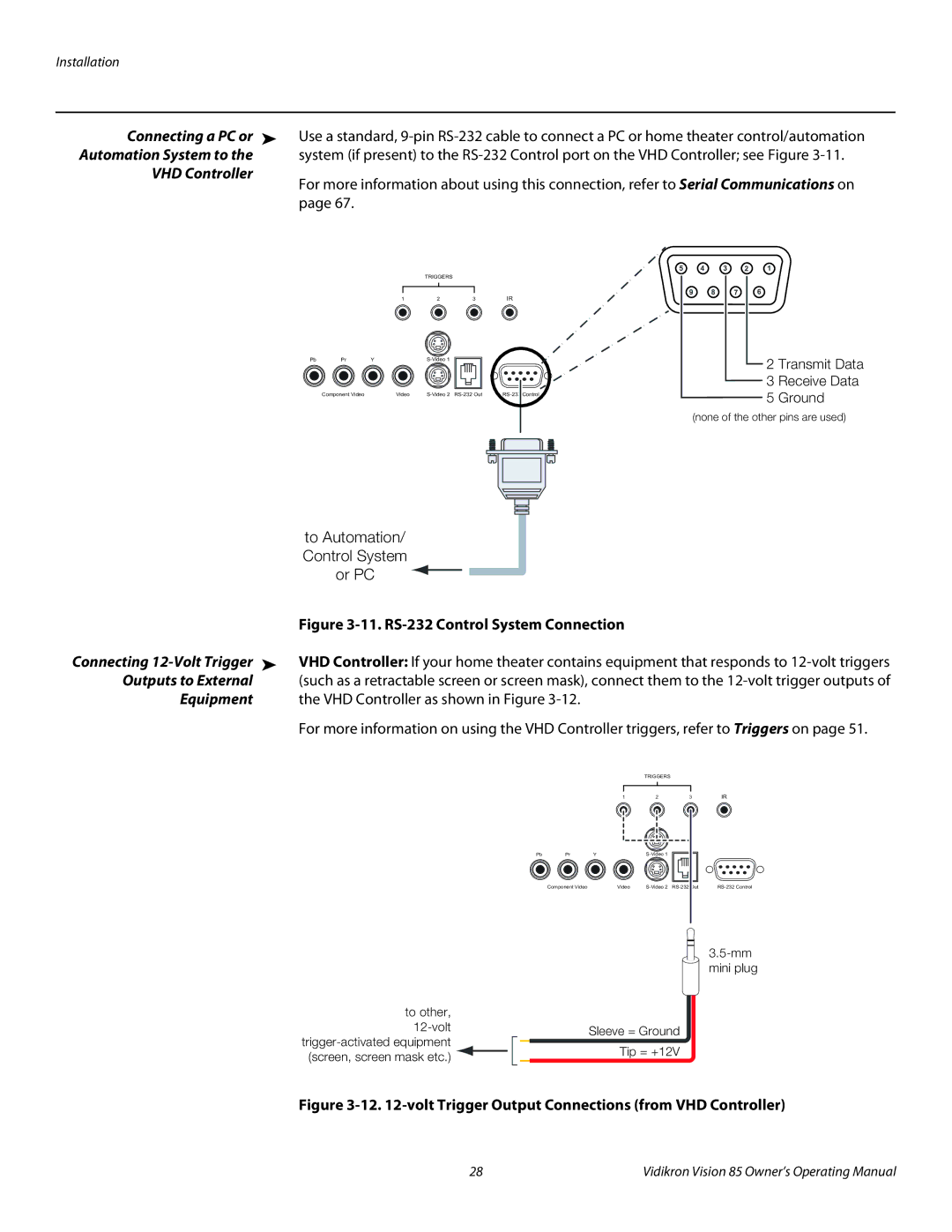
Connecting a PC or ➤ | Use a standard, | ||||
Automation System to the | system (if present) to the | ||||
VHD Controller | For more information about using this connection, refer to Serial Communications on | ||||
| |||||
| page 67. |
|
|
|
|
| 5 | 4 | 3 | 2 | 1 |
|
|
| TRIGGERS |
|
|
|
| 1 | 2 | 3 | IR |
Pb | Pr | Y |
|
| |
| Component Video | Video |
9 8 7 6
2 Transmit Data
3 Receive Data
5 Ground
(none of the other pins are used)
| to Automation/ |
|
|
|
|
| Control System |
|
|
|
|
| or PC |
|
|
|
|
| Figure |
|
|
| |
Connecting | VHD Controller: If your home theater contains equipment that responds to | ||||
Outputs to External | (such as a retractable screen or screen mask), connect them to the | ||||
Equipment | the VHD Controller as shown in Figure |
|
|
|
|
| For more information on using the VHD Controller triggers, refer to Triggers on page 51. | ||||
|
|
| TRIGGERS |
|
|
|
| 1 | 2 | 3 | IR |
| Pb Pr | Y |
|
| |
| Component Video | Video | |||
to other, |
|
| ||
| Sleeve = Ground | |||
|
|
| ||
| Tip = +12V | |||
(screen, screen mask etc.) |
| |||
|
| |||
Figure 3-12. 12-volt Trigger Output Connections (from VHD Controller)
28 | Vidikron Vision 85 Owner’s Operating Manual |