Spinpoint
SpinPoint V40 Product Manual
Table of Contents
Irmware F Eatures
Ervo S Ystem EAD and W Rite O Perations
Smart
Protocol Overview
Programming Requirements
Timing
General Information
Maintenance Precautions
Service and Repair
107
Table of Figures
Page
Manual Organization
User Definition
Scope
Format C/S
Commands and Messages
Terminology and Conventions
Computer Message
Reference
Introduction
Key Features
Description
Hardware Requirements
Standards and Regulations
Specifications
Specification Summary
Logical Configurations
Physical Specifications
Performance Specifications
28.71
Power Requirements
SV6003H SV6014H SV8004H
Environmental Specifications
Mtbf POH
Reliability Specifications
Space Requirements
Installation
Mounting
Unpacking Instructions
Orientation
2Mounting Dimensions in Millimeters
3Mounting-Screw Clearance
Clearance
Ventilation
Cable Connectors
DC Power Connector
AT-Bus Interface Connector
SpinPoint V40 Product Manual
Jumper Block Configurations
Options for Jumper Block Configuration
7DC Power Connector and AT-Bus Interface Cable Connections
Drive Installation
Parameter
System Startup Procedure
System Setup
Disk Drive Operation
Head / Disk Assembly HDA
Base Casting Assembly
DC Spindle Motor Assembly
Exploded Mechanical View
Air Filtration System
Disk Stack Assembly
Head Stack Assembly
Voice Coil Motor and Actuator Latch Assemblies
Drive Electronics
Digital Signal Process and Interface Controller
AT Disk Controller
2SID2001 AT Controller Block Diagram
Host Interface Control Block
Disk Control Block
Buffer Control Block
SpinPoint V40 Product Manual
Frequency Synthesizer
Power Management
Read/Write IC
Disk ECC Control Block
Analog Anti-Aliasing Low Pass Filter
Time Base Generator
Automatic Gain Control
Asymmetry Correction Circuitry ASC
3Read/Write 88C5200
Read and Write Operations
Servo System
Read Channel
Write Channel
Firmware Features
Read Caching
Write Caching
Smart
Defect Management
Automatic Defect Allocation
Multi-burst ECC Correction
Blank
Signal Summary
Signal Conventions
Physical Interface
Signal Descriptions
IOCS16- Drive 16-bit I/O
DMACK- DMA Acknowledge
Dmarq DMA Request
Intrq Drive Interrupt
RESET- Drive Reset
PDIAG- Passed Diagnostics
Iordy I/O Channel Ready
SD2
SD8 SD6 SD9 SD5
SD4
SD3
Drive Host
Drive
DIR
Environment
Logical Interface
General
Bit Conventions
SpinPoint V40 Product Manual
N N N A a a
Command Block Registers
2 I/O Register Address
Control Block Registers
Device Control Register 3F6h
Control Block Register Descriptions
Alternate Status Register 3F6h
Drive Address Register 3F7h
Data Register 1F0h
Command Block Register Descriptions
Features Register 1F1h
Error Register 1F1h
Cylinder Low Register 1F4h
Command Register 1F7h
Sector Count Register 1F2h
Cylinder High Register 1F5h
BSY Drdy DWF DSC DRQ Corr IDX ERR
Status Register 1F7h
At Command Register Descriptions
Command Parameter Used
SpinPoint V40 Product Manual
Execute Device Diagnostics 90h
Check Power Mode 98h, E5h
Download Micro Code 92h
Format Track 50h
Flush Cache E7h
Identify Device ECh
Xxxx
Word Content Description
Capabilities
Command set supported
95-128 0000h Reserved 129-159 Vendor specific 160-255
Idle Immediate 95h,E1h
Idle 97h,E3h
Initialize Device Parameters 91h
Read Long 22hwith retry, 23h without retry
Read Buffer E4h
Read Multiple Command C4h
Read Sectors 20hwith retry, 21hwithout retry
Read Native Max Address F8h
Recalibrate 1xh
Read Verify Sectors 40hwith retry, 41hwithout retry
Seek 7xh
Mode
Set Features EFh
BSY Drdy DRQ ERR
Inputs
LBA
Normal outputs
Description
Sleep 99h, E6h
Set Multiple Mode C6h
Standby 96h,E2h
Smart disable operation D9h
Smart B0h
Smart enable operations D8h
Smart enable/disable attribute autosave D2h
Smart execute off-line immediate D4h
Byte Descriptions
Smart read data D0h
Off-line data collection capability
Value Definition
Smart save attribution value D3h
Smart capability
Smart read log sector D5h
Smart return status DAh
Write DMA CAh
Standby 96h, E2h
Standby Immediate 94h, E0h
Write Buffer E8h
Write Sectors 30hwith retry, 31hwithout retry
Write Multiple Command C5h
SpinPoint V40 Product Manual
Error Posting
Reset Response
Programming Requirements
BBK
Command Error Register Status Register
Idle mode
Power Conditions
Sleep mode
Standby mode
Normal mode
Protocol Overview
PIO Data in Commands
PIO Read Command
PIO Data Out Commands
PIO Read Aborted Command
BSY=0 DRQ=1 BSY=1 DRQ=0
PIO Write Command
PIO Write Aborted Command
BSY=0 DRDY=1 BSY=1
Non-Data Commands
DMA Data Transfer Commands
BSY=0 BSY=1
Aborted DMA Command Initialize DMA Reset DMA Status
BSY=1 BSY=0
Register transfers
Timing
DIOR-/DIOW Write
PIO data transfers
PIO timing parameters Mode
Addr valid See note T1 t2
DIOR-/DIOW
DIOR-/DIOW
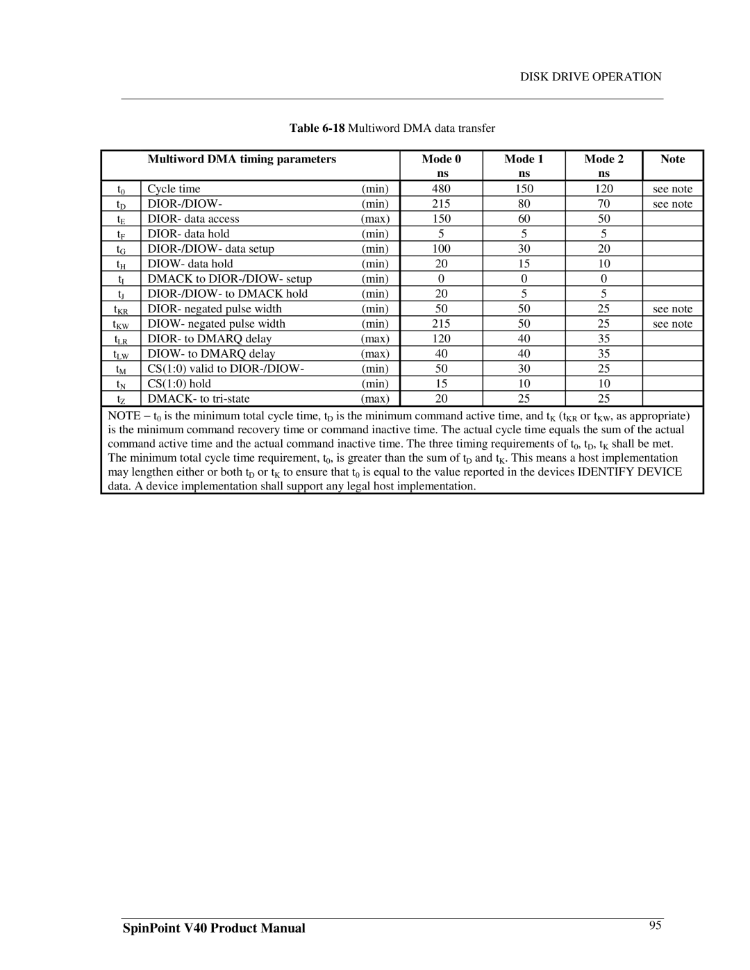
Multiword DMA data transfer
Multiword DMA timing parameters Mode
Initiating an Ultra DMA data in burst
Ultra DMA data transfer
19Ultra DMA data burst timing requirements
Ultra DMA data burst timing requirements
5Sustained Ultra DMA data in burst
Sustained Ultra DMA data in burst
6Host pausing an Ultra DMA data in burst
Host pausing an Ultra DMA data in burst
7Device terminating an Ultra DMA data in burst 100
Device terminating an Ultra DMA data in burst
8Host terminating an Ultra DMA data in burst
Host terminating an Ultra DMA data in burst
9Initiating an Ultra DMA data out burst 102
Initiating an Ultra DMA data out burst
10Sustained Ultra DMA data out burst
Sustained Ultra DMA data out burst
11Device pausing an Ultra DMA data out burst 104
Device pausing an Ultra DMA data out burst
12Host terminating an Ultra DMA data out burst
Host terminating an Ultra DMA data out burst
13Device terminating an Ultra DMA data out burst 106
Device terminating an Ultra DMA data out burst
Service And Repair
Maintenance Precautions
General Information