PART NAMES AND FUNCTIONS
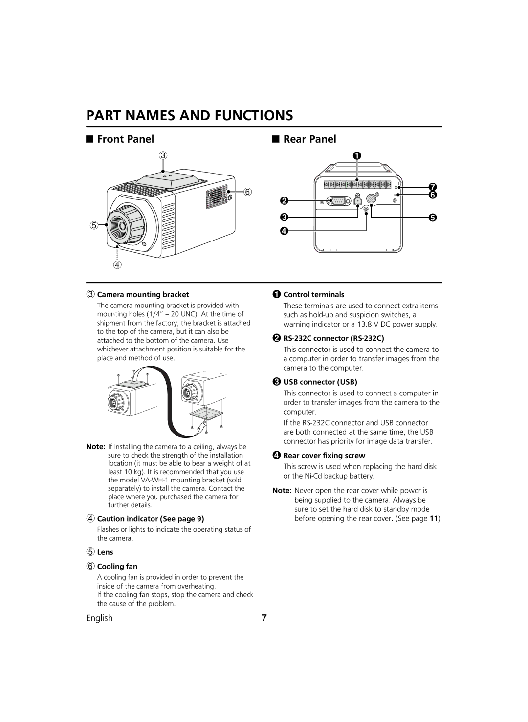
Front Panel |
| Rear Panel |
3
![]()
![]()
![]()
![]() 6
6
1
7
![]()
![]() 6
6
5
2
3
4
5
4
3Camera mounting bracket
The camera mounting bracket is provided with mounting holes (1/4” – 20 UNC). At the time of shipment from the factory, the bracket is attached to the top of the camera, but it can also be attached to the bottom of the camera. Use whichever attachment position is suitable for the place and method of use.
Note: If installing the camera to a ceiling, always be sure to check the strength of the installation location (it must be able to bear a weight of at least 10 kg). It is recommended that you use the model
4Caution indicator (See page 9)
Flashes or lights to indicate the operating status of the camera.
5Lens
6Cooling fan
1Control terminals
These terminals are used to connect extra items such as
2RS-232C connector (RS-232C)
This connector is used to connect the camera to a computer in order to transfer images from the camera to the computer.
3USB connector (USB)
This connector is used to connect a computer in order to transfer images from the camera to the computer.
If the
4Rear cover fixing screw
This screw is used when replacing the hard disk or the
Note: Never open the rear cover while power is being supplied to the camera. Always be sure to set the hard disk to standby mode before opening the rear cover. (See page 11)
A cooling fan is provided in order to prevent the inside of the camera from overheating.
If the cooling fan stops, stop the camera and check the cause of the problem.
English | 7 |