Appendix
Configurations of Terminals
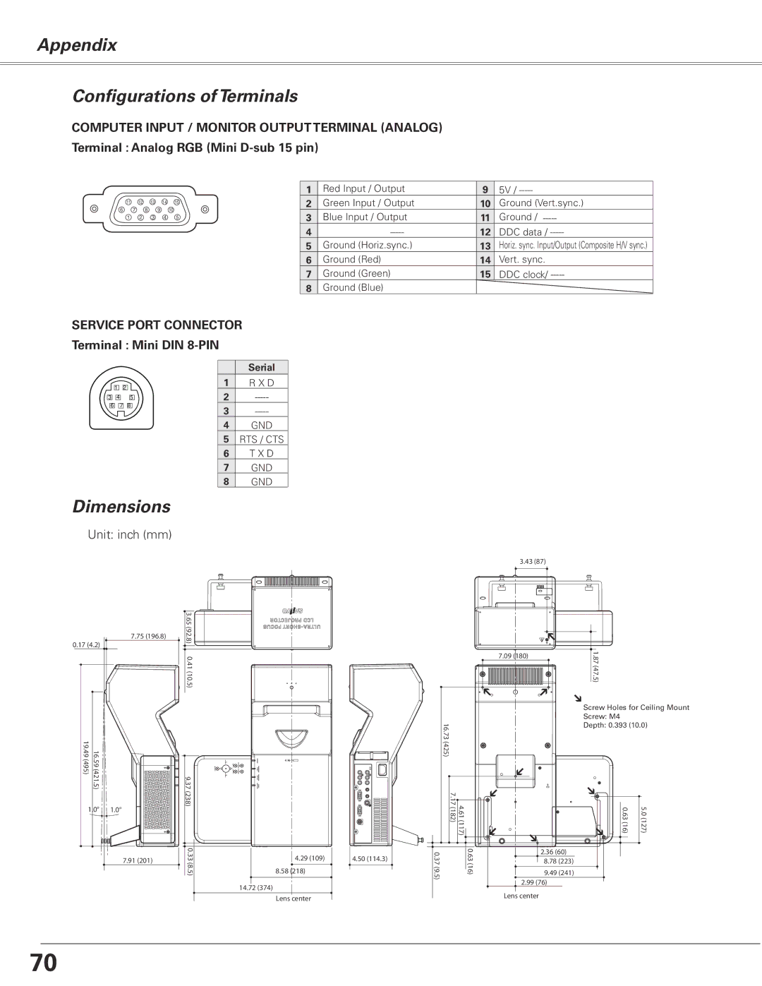
COMPUTER INPUT / MONITOR OUTPUT TERMINAL (ANALOG) Terminal : Analog RGB (Mini
11 12 13 14 15
6 7 8 9 10
1 | 2 | 3 | 4 | 5 |
1 | Red Input / Output | 9 | 5V / |
2 | Green Input / Output | 10 | Ground (Vert.sync.) |
3 | Blue Input / Output | 11 | Ground / |
4 | 12 | DDC data / | |
5 | Ground (Horiz.sync.) | 13 | Horiz. sync. Input/Output (Composite H/V sync.) |
6 | Ground (Red) | 14 | Vert. sync. |
7 | Ground (Green) | 15 | DDC clock/ |
8 | Ground (Blue) |
|
|
SERVICE PORT CONNECTOR Terminal : Mini DIN 8-PIN
|
|
|
| Serial |
| 1 | 2 | 1 | R X D |
3 | 4 | 5 | 2 | |
6 | 7 | 8 | 3 | |
|
|
| ||
|
|
| 4 | GND |
|
|
| 5 | RTS / CTS |
|
|
| 6 | T X D |
|
|
| 7 | GND |
|
|
| 8 | GND |
Dimensions
Unit: inch (mm)
| 7.75 (196.8) |
0.17 (4.2) |
|
16.59 (421 19.49 (495) |
|
.5) |
|
1.0° | 1.0° |
| 7.91 (201) |
![]() 3.65 (92.8) 0.41 (10.5)
3.65 (92.8) 0.41 (10.5)![]()
9.37 (238) |
|
0.33 | 4.29 (109) |
(8.5) | 8.58 (218) |
| 14.72 (374) |
| Lens center |
4.50 (114.3) |
3.43 (87) |
| |
7.09 (180) | 1. | |
87 (47.5) | ||
|
| Screw Holes for Ceiling Mount |
| Screw: M4 |
16.73 (425) | Depth: 0.393 (10.0) |
|
7.17 (182) | 4.61 (117) | 0.63 (16) | 5.0 (127) |
|
|
|
|
|
|
|
|
|
|
|
|
|
|
|
0.37 (9.5) | 0.63 (16) |
|
|
|
|
| 2.36 (60) |
|
|
| ||||
|
|
|
|
| 8.78 (223) |
|
|
| ||||||
|
| |||||||||||||
|
| 9.49 (241) |
|
|
| |||||||||
|
|
|
|
|
| |||||||||
|
|
|
| 2.99 (76) |
|
|
|
|
|
|
| |||
|
|
|
| Lens center | ||||||||||
70