Chapter 5 Appendix
Use of telnet
You can control the projector by using the telnet application*1 installed on your computer. Normally, the telnet application is available on your computer.
* The telnet 10000 port is used to control the projector.
Control
(For example, in case of using the telnet application of Windows XP Professional.)
1.Select Run... submenu from Start menu on the computer. Type "telnet" onto the Open text area on the displayed window and press OK button.
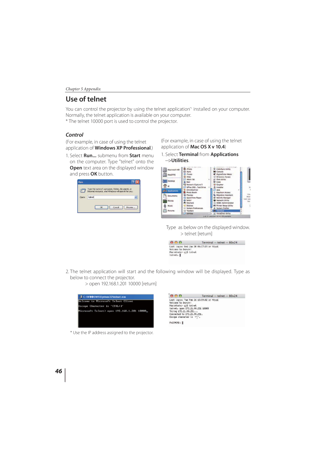
(For example, in case of using the telnet application of Mac OS X v 10.4)
1.Select Terminal from Applications
Type as below on the displayed window. > telnet [return]
2.The telnet application will start and the following window will be displayed. Type as below to connect the projector.
>open 192.168.1.201 10000 [return]
* Use the IP address assigned to the projector.
46