CONNECTIONS
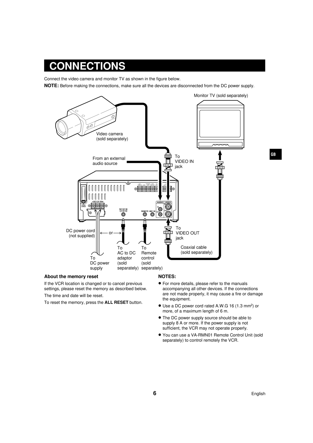
Connect the video camera and monitor TV as shown in the figure below.
NOTE: Before making the connections, make sure all the devices are disconnected from the DC power supply.
Monitor TV (sold separately)
Video camera (sold separately)
From an external audio source
|
|
|
|
|
|
|
|
To |
|
|
|
|
| GB | |
|
|
|
|
|
| ||
VIDEO IN |
|
|
|
|
|
| |
jack |
|
|
|
|
|
| |
|
|
|
|
|
| ||
EXT | WARNING | TAPE | SW | ALARM |
|
TIMER IN COM | OUT | END OUT | OUT COM | OUT | IN |
DC12V IN | AUDIO VIDEO | |
| ||
PUSH | IN | |
| ||
OPEN | IN | |
| ||
DC12V IN | OUT | |
REMOTE MIC IN | ||
OUT |
DC power cord |
| or |
|
|
|
|
|
|
|
|
|
|
|
|
|
| |||
|
|
|
|
|
|
| |||
|
|
|
|
|
|
| |||
(not supplied) |
|
|
|
|
|
|
| ||
|
|
|
|
|
|
|
| ||
|
|
|
|
|
|
|
|
|
|
|
|
| To | To | |||||
|
|
| AC to DC | Remote | |||||
To |
| adaptor | control | ||||||
DC power | (sold | (sold | |||||||
supply |
| separately) | separately) | ||||||
To
VIDEO OUT jack
Coaxial cable (sold separately)
About the memory reset
If the VCR location is changed or to cancel previous settings, please reset the memory as described below.
The time and date will be reset.
To reset the memory, press the ALL RESET button.
NOTES:
•For more details, please refer to the manuals accompanying all other devices. If the connections are not made properly, it may cause a fire or damage the equipment.
•Use a DC power cord rated A.W.G 16 (1.3 mm2) or more, of a maximum length of 6 m.
•The DC power supply source should be able to supply 8 A or more. If the power supply is not sufficient, the VCR may not operate properly.
•You can use a
6 | English |