LOCATIONS OF CONTROLS AND INDICATORS
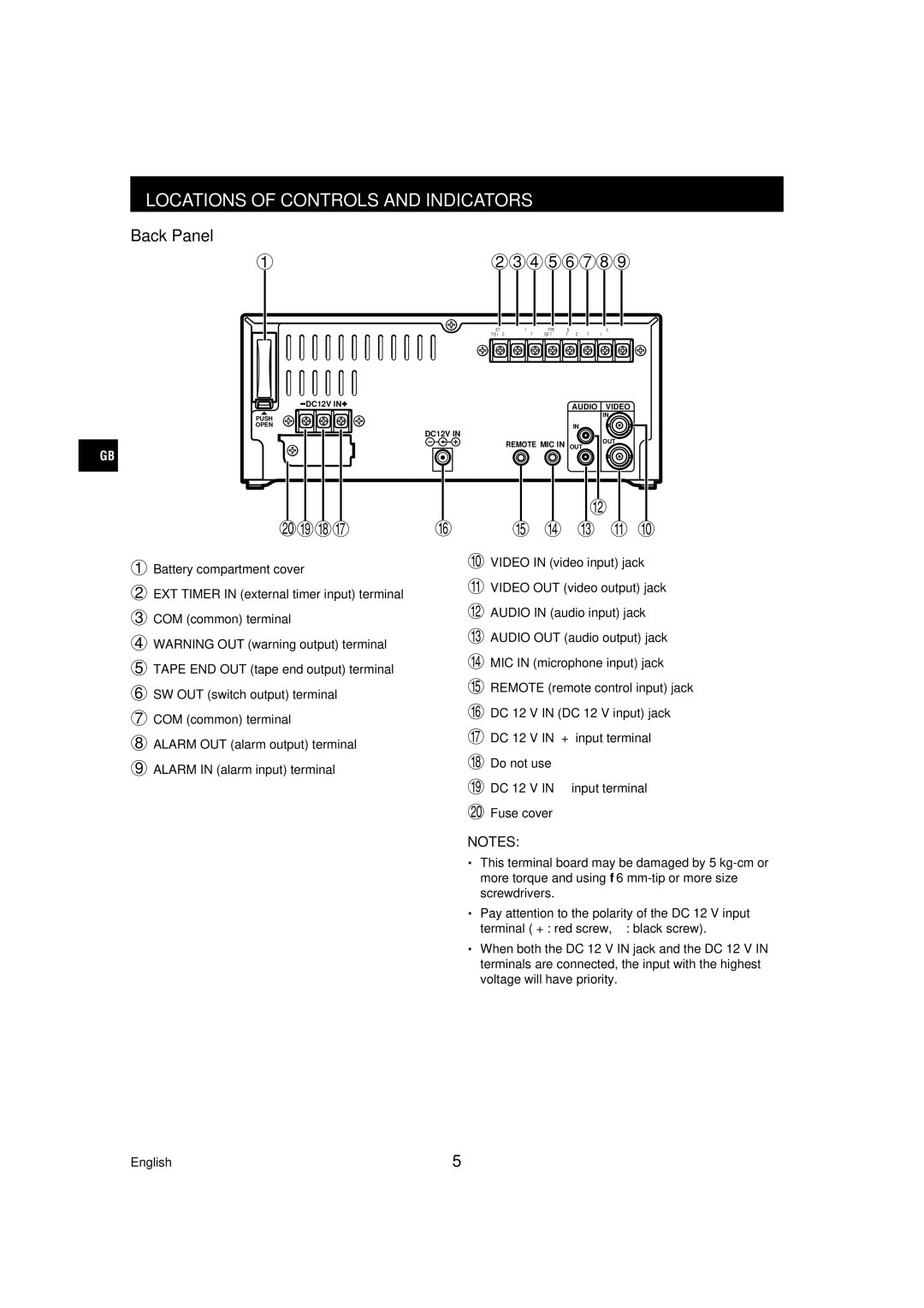
Back Panel
123456789
EXT | WARNING | TAPE | SW | ALARM |
|
TIMER IN COM | OUT | END OUT | OUT COM | OUT | IN |
DC12V IN | AUDIO VIDEO | |
PUSH | IN | |
| ||
OPEN | IN | |
DC12V IN | ||
OUT | ||
REMOTE MIC IN | ||
OUT | ||
GB |
|
|
|
|
|
|
|
|
|
|
|
|
|
|
|
|
|
|
|
|
|
|
|
|
|
|
|
|
|
|
|
|
|
|
|
|
|
|
|
|
|
|
|
|
|
|
|
|
|
|
|
|
|
|
|
|
|
|
|
| H |
|
|
|
|
|
|
| PONM | L | K J I G F | ||||||||||
1 Battery compartment cover |
|
|
| F VIDEO IN (video input) jack | |||||||||||
|
|
|
|
|
|
|
|
|
|
| |||||
2 EXT TIMER IN (external timer input) terminal |
|
|
| G VIDEO OUT (video output) jack | |||||||||||
|
|
|
|
|
|
|
|
|
|
| |||||
3 COM (common) terminal |
|
|
| H AUDIO IN (audio input) jack | |||||||||||
|
|
|
|
|
|
|
|
|
|
| |||||
4 WARNING OUT (warning output) terminal |
|
|
| I AUDIO OUT (audio output) jack | |||||||||||
|
|
|
|
|
|
|
|
|
|
| |||||
5 TAPE END OUT (tape end output) terminal |
|
|
| J MIC IN (microphone input) jack | |||||||||||
|
|
|
|
|
|
|
|
|
|
| |||||
6 SW OUT (switch output) terminal |
|
|
| K REMOTE (remote control input) jack | |||||||||||
|
|
|
|
|
|
|
|
|
|
| |||||
7 COM (common) terminal |
|
|
| L DC 12 V IN (DC 12 V input) jack | |||||||||||
|
|
|
|
|
|
|
|
|
|
| |||||
8 ALARM OUT (alarm output) terminal |
|
|
| M DC 12 V IN “+” input terminal | |||||||||||
|
|
|
|
|
|
|
|
|
|
| |||||
9 ALARM IN (alarm input) terminal |
|
|
| N Do not use | |||||||||||
|
|
|
|
|
|
|
|
|
|
| |||||
|
|
|
|
|
|
|
| O DC 12 V IN | |||||||
|
|
|
|
|
|
|
| P Fuse cover | |||||||
|
|
|
|
|
|
|
| NOTES: | |||||||
•
•
•
This terminal board may be damaged by 5
Pay attention to the polarity of the DC 12 V input terminal (“+”: red screw,
When both the DC 12 V IN jack and the DC 12 V IN terminals are connected, the input with the highest voltage will have priority.
English | 5 |