Unit 6: Maintenance
REPLACEMENT PROCEDURES
The printer contains replaceable components and
FUSE REPLACEMENT
The printer has three fuses; one is externally accessible and is wired to the power supply while the other two are located internally and directly connected to the main circuit board.
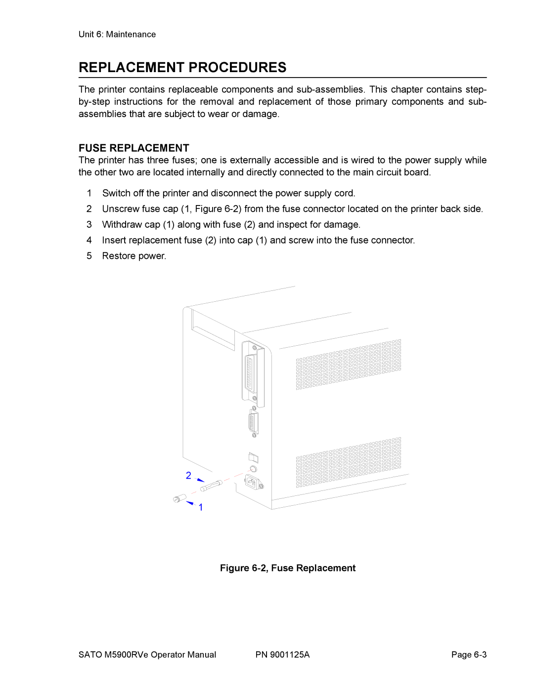
1Switch off the printer and disconnect the power supply cord.
2Unscrew fuse cap (1, Figure
3Withdraw cap (1) along with fuse (2) and inspect for damage.
4Insert replacement fuse (2) into cap (1) and screw into the fuse connector.
5Restore power.
2![]()
![]() 1
1
Figure 6-2, Fuse Replacement
SATO M5900RVe Operator Manual | PN 9001125A | Page |