Unit 1: Introduction
CONTROL FEATURES
SWITCHES
Power Switch | Two position on/off switch that controls power flow to the system. |
Line Key | Toggles between |
| printer is ready to receive data from the host. Acts as a pause during |
| print by taking the printer |
| interface for printer setup. |
|
|
Feed Key | Feeds one blank label through the printer when |
| printer is |
| used as a |
|
|
DSW2 & DSW3 | Sets operational parameters of printer. |
DSW1 | To configure optional RS232 communication card. Located on card. |
|
|
CONNECTION PORTS |
|
|
|
AC Power Input | Connector permits 115V, 50/60 Hz supply via supplied cord. |
Interface Port | Connector for interface harness. Must be connected for the printer to |
| be operational. Acceptable interface types are: |
| • RS232C Serial I/F Module, |
| • IEEE1284 Parallel I/F Module, AMP |
| • Universal Serial Bus Adapter |
| • Ethernet 10/100 BaseT I/F Module |
| • RS422/485 I/F Module, |
|
|
Ext. Interface Port | Connector for external control of print cycle. Also supplies power for |
| optional accessories - AMP |
Memory Card Slot | Slot for the insertion of optional PCMCIA Memory Card |
|
|
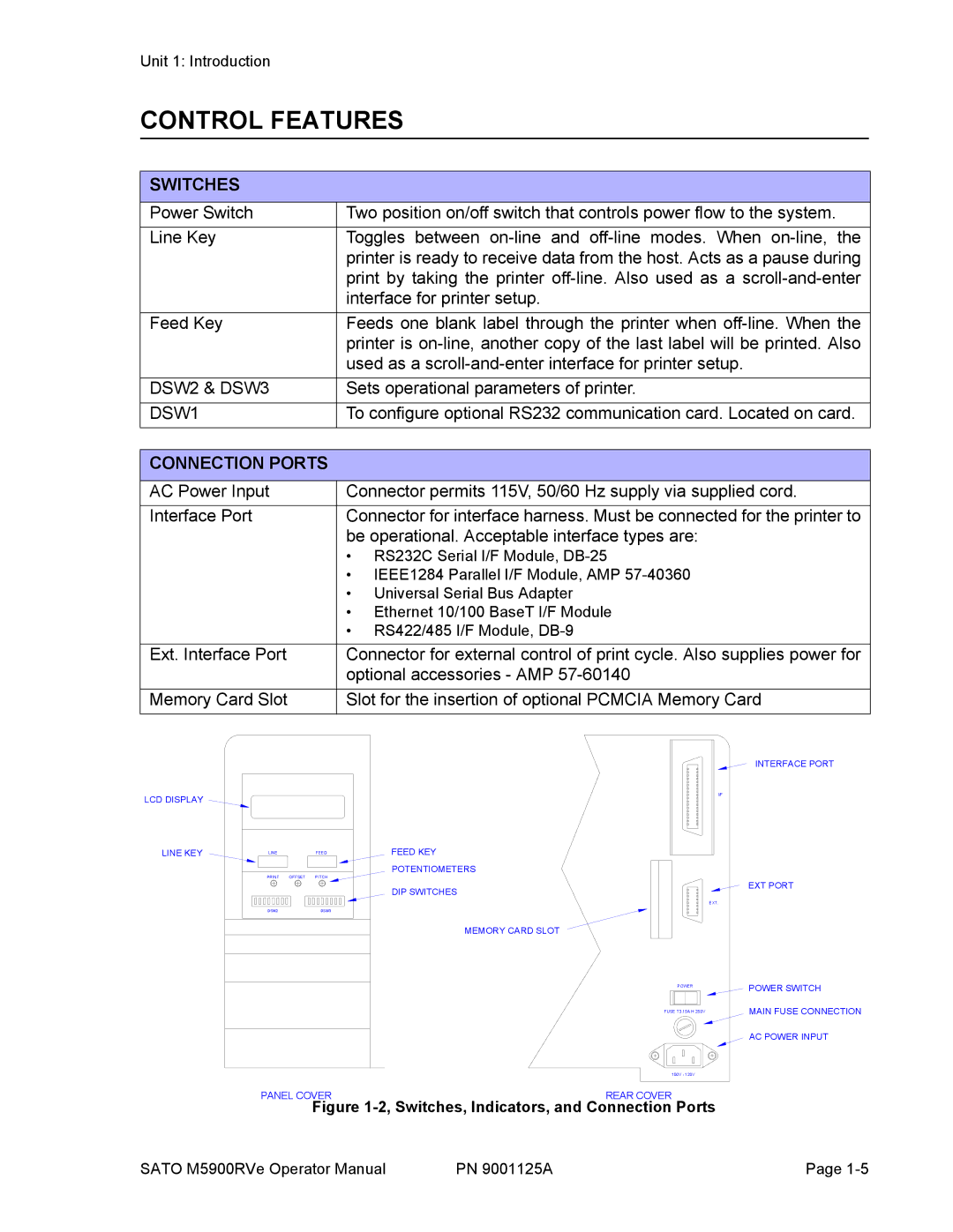
LCD DISPLAY
LINE KEY
LINEFEED
PRINT OFFSET PITCH
DSW2DSW3
FEED KEY
POTENTIOMETERS
DIP SWITCHES
MEMORY CARD SLOT
I/F
EXT.
POWER
FUSE T3.15A H 250V
100V - 120V
INTERFACE PORT
EXT PORT
POWER SWITCH
MAIN FUSE CONNECTION AC POWER INPUT
PANEL COVERREAR COVER
Figure 1-2, Switches, Indicators, and Connection Ports
SATO M5900RVe Operator Manual | PN 9001125A | Page |