WebSTAR DPR300 Series Cable Modem Gateway User’s Guide
Back Panel Description
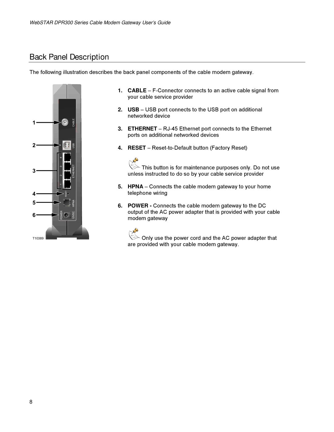
The following illustration describes the back panel components of the cable modem gateway.
1 |
| CABLE |
|
| |
2 |
| USB |
| 4 | ETHERNET |
3 | 2 3 | |
|
| |
| 1 |
|
4 |
| RESET |
5 |
| HPNA |
|
| |
6 | POWER | 12VDC |
|
|
T10389
1.CABLE –
2.USB – USB port connects to the USB port on additional networked device
3.ETHERNET –
4.RESET –
![]()
![]() This button is for maintenance purposes only. Do not use unless instructed to do so by your cable service provider
This button is for maintenance purposes only. Do not use unless instructed to do so by your cable service provider
5.HPNA – Connects the cable modem gateway to your home telephone wiring
6.POWER - Connects the cable modem gateway to the DC output of the AC power adapter that is provided with your cable modem gateway
![]()
![]() Only use the power cord and the AC power adapter that are provided with your cable modem gateway.
Only use the power cord and the AC power adapter that are provided with your cable modem gateway.
8
