Philips Semiconductors | User’s Manual - Preliminary - |
|
|
RESET | P89LPC906/907/908 |
9. RESET
The P1.5/RST pin can function as either an active low reset input or as a digital input, P1.5. The RPE (Reset Pin Enable) bit in UCFG1, when set to 1, enables the external reset input function on P1.5. When cleared, P1.5 may be used as an input pin.
NOTE: During a
NOTE: During a power cycle, VDD must fall below VPOR (see "DC electrical characteristics" in the datasheet) before pwoer is reapplied, in order to ensure a
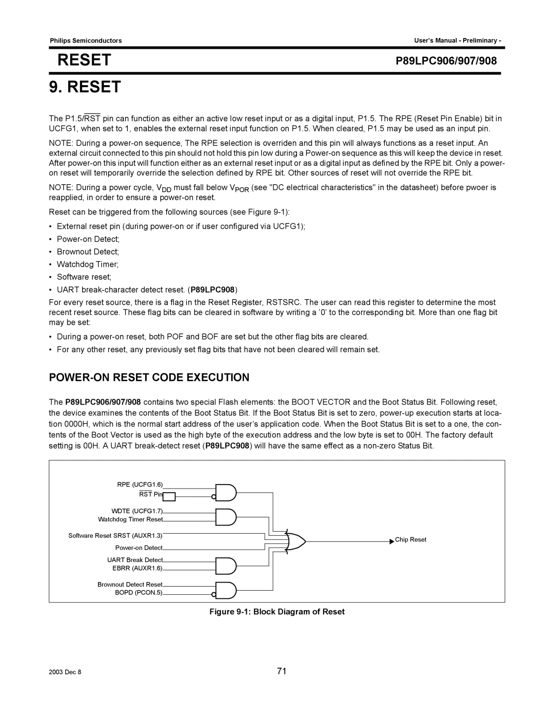
Reset can be triggered from the following sources (see Figure
•External reset pin (during
•
•Brownout Detect;
•Watchdog Timer;
•Software reset;
•UART
For every reset source, there is a flag in the Reset Register, RSTSRC. The user can read this register to determine the most recent reset source. These flag bits can be cleared in software by writing a ’0’ to the corresponding bit. More than one flag bit may be set:
•During a
•For any other reset, any previously set flag bits that have not been cleared will remain set.
POWER-ON RESET CODE EXECUTION
The P89LPC906/907/908 contains two special Flash elements: the BOOT VECTOR and the Boot Status Bit. Following reset, the device examines the contents of the Boot Status Bit. If the Boot Status Bit is set to zero,
RPE (UCFG1.6) |
RST Pin |
WDTE (UCFG1.7)
Watchdog Timer Reset
Software Reset SRST (AUXR1.3)
UART Break Detect
EBRR (AUXR1.6)
Brownout Detect Reset![]()
![]()
![]()
BOPD (PCON.5)
![]() Chip Reset
Chip Reset
Figure 9-1: Block Diagram of Reset
2003 Dec 8 | 71 |