Philips Semiconductors |
|
|
|
|
|
|
|
| User’s Manual - Preliminary - |
| |||||
|
|
|
|
|
|
|
|
|
|
|
|
|
|
| |
GENERAL DESCRIPTION |
|
|
|
|
| P89LPC906/907/908 |
|
| |||||||
|
|
|
|
|
|
|
|
|
|
|
|
|
| ||
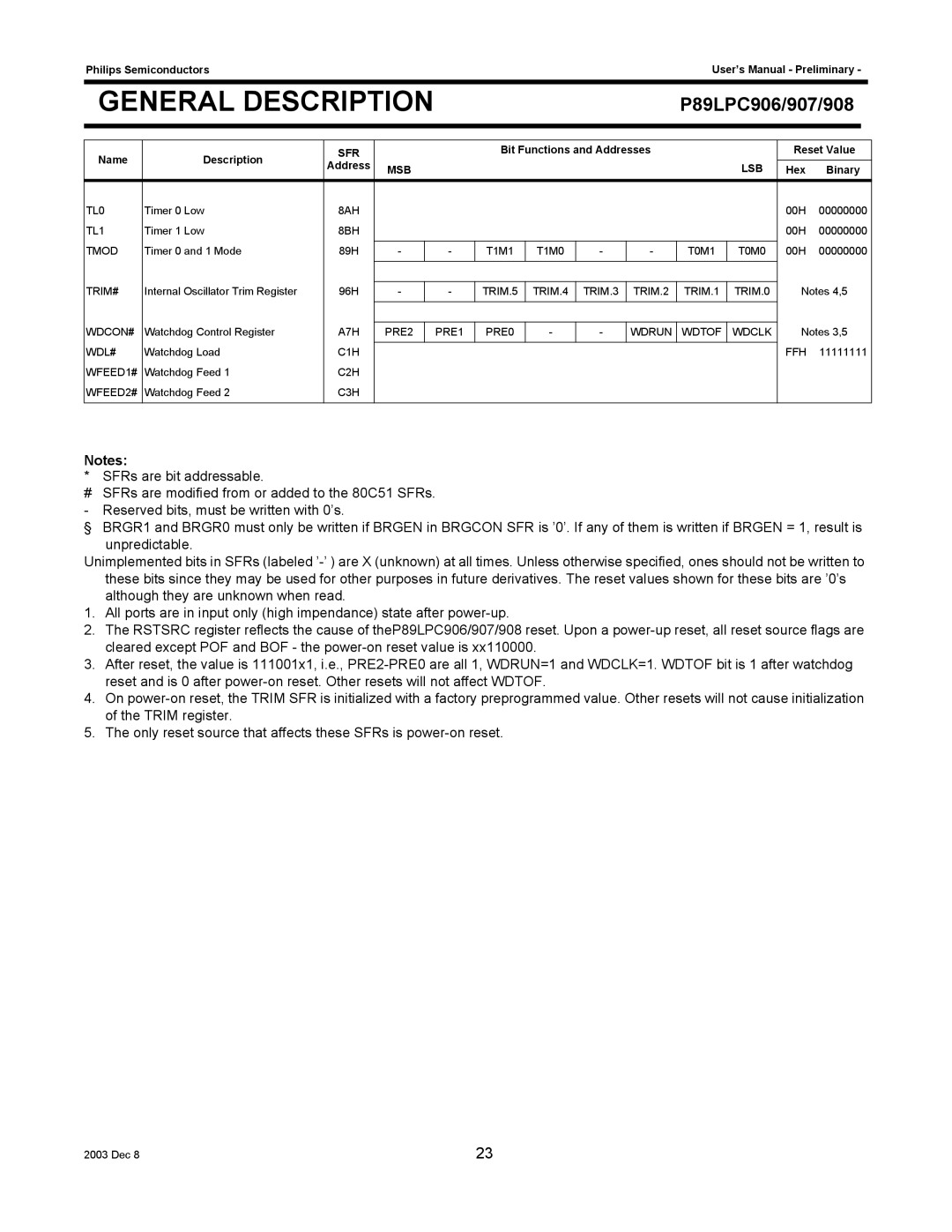
Name | Description | SFR |
|
|
| Bit Functions and Addresses |
|
| Reset Value |
| |||||
Address | MSB |
|
|
|
|
|
| LSB | Hex | Binary |
| ||||
|
|
|
|
|
|
|
|
| |||||||
TL0 | Timer 0 Low | 8AH |
|
|
|
|
|
|
|
|
| 00H | 00000000 |
| |
TL1 | Timer 1 Low | 8BH |
|
|
|
|
|
|
|
|
| 00H | 00000000 |
| |
|
|
|
|
|
|
|
|
|
|
|
|
|
|
| |
TMOD | Timer 0 and 1 Mode | 89H | - |
| - | T1M1 | T1M0 | - | - | T0M1 | T0M0 | 00H | 00000000 |
| |
|
|
|
|
|
|
|
|
|
|
|
|
|
| ||
|
|
|
|
|
|
|
|
|
|
|
|
|
| ||
TRIM# | Internal Oscillator Trim Register | 96H | - |
| - | TRIM.5 | TRIM.4 | TRIM.3 | TRIM.2 | TRIM.1 | TRIM.0 | Notes 4,5 |
| ||
|
|
|
|
|
|
|
|
|
|
|
|
|
| ||
|
|
|
|
|
|
|
|
|
|
|
|
| |||
WDCON# | Watchdog Control Register | A7H | PRE2 |
| PRE1 | PRE0 | - | - | WDRUN | WDTOF | WDCLK | Notes 3,5 |
| ||
WDL# | Watchdog Load | C1H |
|
|
|
|
|
|
|
|
| FFH | 11111111 |
| |
|
|
|
|
|
|
|
|
|
| ||||||
WFEED1# | Watchdog Feed 1 | C2H |
|
|
|
|
|
|
|
|
|
|
|
|
|
WFEED2# | Watchdog Feed 2 | C3H |
|
|
|
|
|
|
|
|
|
|
|
|
|
|
|
|
|
|
|
|
|
|
|
|
|
|
|
|
|
Notes:
* SFRs are bit addressable.
#SFRs are modified from or added to the 80C51 SFRs. - Reserved bits, must be written with 0’s.
§ BRGR1 and BRGR0 must only be written if BRGEN in BRGCON SFR is ’0’. If any of them is written if BRGEN = 1, result is unpredictable.
Unimplemented bits in SFRs (labeled
1. All ports are in input only (high impendance) state after
2. The RSTSRC register reflects the cause of theP89LPC906/907/908 reset. Upon a
3. After reset, the value is 111001x1, i.e.,
4. On
5. The only reset source that affects these SFRs is
2003 Dec 8 | 23 |