Philips Semiconductors | User’s Manual - Preliminary - | |
|
|
|
UART | P89LPC906/907/908 |
|
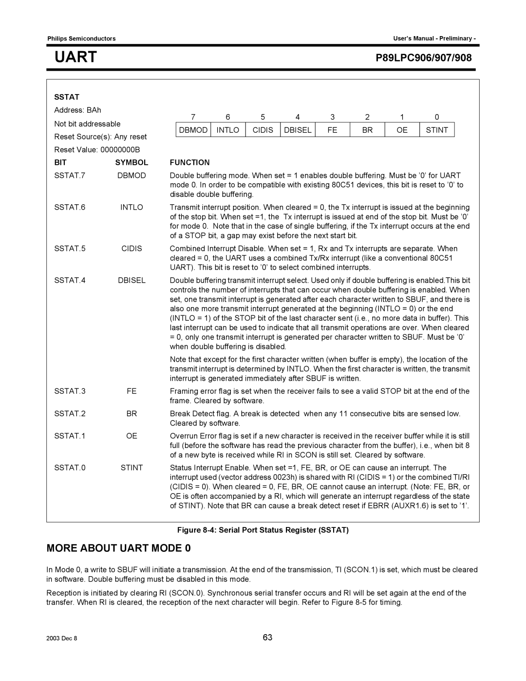
SSTAT
Address: BAh
Not bit addressable
Reset Source(s): Any reset
Reset Value: 00000000B
7 | 6 | 5 | 4 | 3 | 2 | 1 | 0 |
DBMOD | INTLO | CIDIS | DBISEL | FE | BR | OE | STINT |
|
|
|
|
|
|
|
|
BIT | SYMBOL | FUNCTION |
SSTAT.7 | DBMOD | Double buffering mode. When set = 1 enables double buffering. Must be ’0’ for UART |
|
| mode 0. In order to be compatible with existing 80C51 devices, this bit is reset to ’0’ to |
|
| disable double buffering. |
SSTAT.6 | INTLO | Transmit interrupt position. When cleared = 0, the Tx interrupt is issued at the beginning |
|
| of the stop bit. When set =1, the Tx interrupt is issued at end of the stop bit. Must be ’0’ |
|
| for mode 0. Note that in the case of single buffering, if the Tx interrupt occurs at the end |
|
| of a STOP bit, a gap may exist before the next start bit. |
SSTAT.5 | CIDIS | Combined Interrupt Disable. When set = 1, Rx and Tx interrupts are separate. When |
|
| cleared = 0, the UART uses a combined Tx/Rx interrupt (like a conventional 80C51 |
|
| UART). This bit is reset to ’0’ to select combined interrupts. |
SSTAT.4 | DBISEL | Double buffering transmit interrupt select. Used only if double buffering is enabled.This bit |
|
| controls the number of interrupts that can occur when double buffering is enabled. When |
|
| set, one transmit interrupt is generated after each character written to SBUF, and there is |
|
| also one more transmit interrupt generated at the beginning (INTLO = 0) or the end |
|
| (INTLO = 1) of the STOP bit of the last character sent (i.e., no more data in buffer). This |
|
| last interrupt can be used to indicate that all transmit operations are over. When cleared |
|
| = 0, only one transmit interrupt is generated per character written to SBUF. Must be ’0’ |
|
| when double buffering is disabled. |
|
| Note that except for the first character written (when buffer is empty), the location of the |
|
| transmit interrupt is determined by INTLO. When the first character is written, the transmit |
|
| interrupt is generated immediately after SBUF is written. |
SSTAT.3 | FE | Framing error flag is set when the receiver fails to see a valid STOP bit at the end of the |
|
| frame. Cleared by software. |
SSTAT.2 | BR | Break Detect flag. A break is detected when any 11 consecutive bits are sensed low. |
|
| Cleared by software. |
SSTAT.1 | OE | Overrun Error flag is set if a new character is received in the receiver buffer while it is still |
|
| full (before the software has read the previous character from the buffer), i.e., when bit 8 |
|
| of a new byte is received while RI in SCON is still set. Cleared by software. |
SSTAT.0 | STINT | Status Interrupt Enable. When set =1, FE, BR, or OE can cause an interrupt. The |
|
| interrupt used (vector address 0023h) is shared with RI (CIDIS = 1) or the combined TI/RI |
|
| (CIDIS = 0). When cleared = 0, FE, BR, OE cannot cause an interrupt. (Note: FE, BR, or |
|
| OE is often accompanied by a RI, which will generate an interrupt regardless of the state |
|
| of STINT). Note that BR can cause a break detect reset if EBRR (AUXR1.6) is set to ’1’. |
Figure 8-4: Serial Port Status Register (SSTAT)
MORE ABOUT UART MODE 0
In Mode 0, a write to SBUF will initiate a transmission. At the end of the transmission, TI (SCON.1) is set, which must be cleared in software. Double buffering must be disabled in this mode.
Reception is initiated by clearing RI (SCON.0). Synchronous serial transfer occurs and RI will be set again at the end of the transfer. When RI is cleared, the reception of the next character will begin. Refer to Figure
2003 Dec 8 | 63 |