Philips Semiconductors | User’s Manual - Preliminary - | |
|
|
|
P89LPC906/907/908 |
| |
|
|
|
|
| |
|
|
| Reset |
|
|
RTCH |
| RTCL | RTC Reset |
| XTAL2 XTAL1 |
Reload on underflow |
|
|
| ||
|
|
|
|
| Low freq. |
|
|
|
|
| Med. freq. |
MSB |
| LSB |
| High freq. | |
|
| ÷ 128 |
| CCLK | |
Wake up from |
|
|
|
| Int. Osc’s |
|
|
|
|
| |
| RTCF | RTCEN | RTCS1 | RTCS2 | |
|
| ||||
Interrupt | ERTC | RTC underflow flag | RTC Enable | RTC clk select | |
if enabled |
|
|
|
|
|
(shared w. WDT) |
|
|
|
|
|
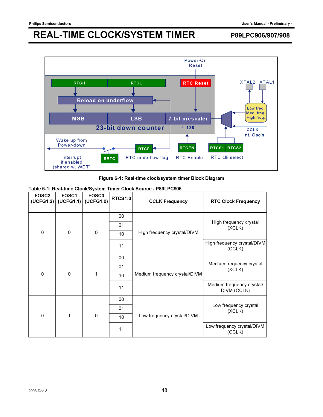
Figure 6-1: Real-time clock/system timer Block Diagram
Table 6-1: Real-time Clock/System Timer Clock Source - P89LPC906
FOSC2 | FOSC1 | FOSC0 | RTCS1:0 |
|
|
(UCFG1.2) | (UCFG1.1) | (UCFG1.0) | CCLK Frequency | RTC Clock Frequency | |
|
|
|
|
|
|
|
|
| 00 |
| High frequency crystal |
|
|
|
|
| |
|
|
| 01 |
| |
|
|
|
| (XCLK) | |
0 | 0 | 0 |
| High frequency crystal/DIVM | |
10 |
| ||||
|
|
|
|
|
|
|
|
| 11 |
| High frequency crystal/DIVM |
|
|
|
| (CCLK) | |
|
|
|
|
| |
|
|
|
|
|
|
|
|
| 00 |
| Medium frequency crystal |
|
|
|
|
| |
|
|
| 01 |
| |
|
|
|
| (XCLK) | |
0 | 0 | 1 |
| Medium frequency crystal/DIVM | |
10 |
| ||||
|
|
|
|
|
|
|
|
| 11 |
| Medium frequency crystal/ |
|
|
|
| DIVM (CCLK) | |
|
|
|
|
| |
|
|
|
|
|
|
|
|
| 00 |
| Low frequency crystal |
|
|
|
|
| |
|
|
| 01 |
| |
|
|
|
| (XCLK) | |
0 | 1 | 0 |
| Low frequency crystal/DIVM | |
10 |
| ||||
|
|
|
|
|
|
|
|
| 11 |
| Low frequency crystal/DIVM |
|
|
|
| (CCLK) | |
|
|
|
|
| |
|
|
|
|
|
|
2003 Dec 8 | 48 |
