Philips Semiconductors | User’s Manual - Preliminary - | |
|
|
|
UART | P89LPC906/907/908 |
|
.
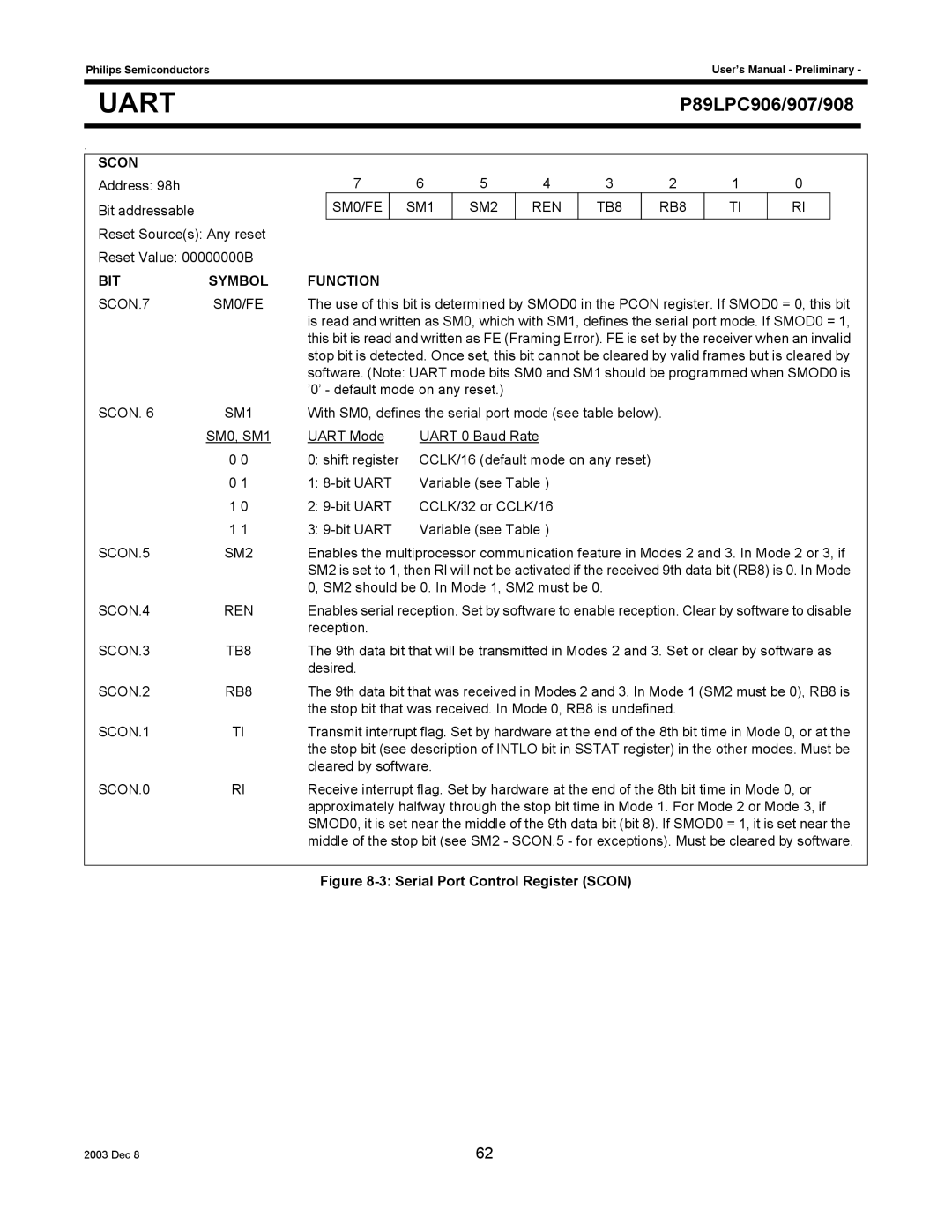
SCON
Address: 98h Bit addressable
Reset Source(s): Any reset
Reset Value: 00000000B
7 | 6 | 5 | 4 | 3 | 2 | 1 | 0 |
SM0/FE | SM1 | SM2 | REN | TB8 | RB8 | TI | RI |
|
|
|
|
|
|
|
|
BIT | SYMBOL | FUNCTION |
|
SCON.7 | SM0/FE | The use of this bit is determined by SMOD0 in the PCON register. If SMOD0 = 0, this bit | |
|
| is read and written as SM0, which with SM1, defines the serial port mode. If SMOD0 = 1, | |
|
| this bit is read and written as FE (Framing Error). FE is set by the receiver when an invalid | |
|
| stop bit is detected. Once set, this bit cannot be cleared by valid frames but is cleared by | |
|
| software. (Note: UART mode bits SM0 and SM1 should be programmed when SMOD0 is | |
|
| ’0’ - default mode on any reset.) | |
SCON. 6 | SM1 | With SM0, defines the serial port mode (see table below). | |
| SM0, SM1 | UART Mode | UART 0 Baud Rate |
| 0 0 | 0: shift register | CCLK/16 (default mode on any reset) |
| 0 1 | 1: | Variable (see Table ) |
| 1 0 | 2: | CCLK/32 or CCLK/16 |
| 1 1 | 3: | Variable (see Table ) |
SCON.5 | SM2 | Enables the multiprocessor communication feature in Modes 2 and 3. In Mode 2 or 3, if | |
|
| SM2 is set to 1, then Rl will not be activated if the received 9th data bit (RB8) is 0. In Mode | |
|
| 0, SM2 should be 0. In Mode 1, SM2 must be 0. | |
SCON.4 | REN | Enables serial reception. Set by software to enable reception. Clear by software to disable | |
|
| reception. |
|
SCON.3 | TB8 | The 9th data bit that will be transmitted in Modes 2 and 3. Set or clear by software as | |
|
| desired. |
|
SCON.2 | RB8 | The 9th data bit that was received in Modes 2 and 3. In Mode 1 (SM2 must be 0), RB8 is | |
|
| the stop bit that was received. In Mode 0, RB8 is undefined. | |
SCON.1 | TI | Transmit interrupt flag. Set by hardware at the end of the 8th bit time in Mode 0, or at the | |
|
| the stop bit (see description of INTLO bit in SSTAT register) in the other modes. Must be | |
|
| cleared by software. | |
SCON.0 | RI | Receive interrupt flag. Set by hardware at the end of the 8th bit time in Mode 0, or | |
|
| approximately halfway through the stop bit time in Mode 1. For Mode 2 or Mode 3, if | |
SMOD0, it is set near the middle of the 9th data bit (bit 8). If SMOD0 = 1, it is set near the middle of the stop bit (see SM2 - SCON.5 - for exceptions). Must be cleared by software.
Figure 8-3: Serial Port Control Register (SCON)
2003 Dec 8 | 62 |