Philips Semiconductors | User’s Manual - Preliminary - | |
|
|
|
ANALOG COMPARATORS | P89LPC906/907/908 | |
10. ANALOG COMPARATORS |
|
|
An analog comparator is provided on the P89LPC906/907/908 . Comparator operation is such that the output is a logical one when the positive input is greater than the negative input (selectable from a pin or an internal reference voltage). Otherwise the output is a zero. The output may be read in a register. The output may also be routed to a pin. The comparator may be configured to cause an interrupt when the output value changes.
The connections to the comparator are shown in Figure
When the comparator is first enabled, the comparator output and interrupt flag are not guaranteed to be stable for 10 microseconds. The comparator interrupt should not be enabled during that time, and the comparator interrupt flag must be cleared before the interrupt is enabled in order to prevent an immediate interrupt service.
COMPARATOR CONFIGURATION
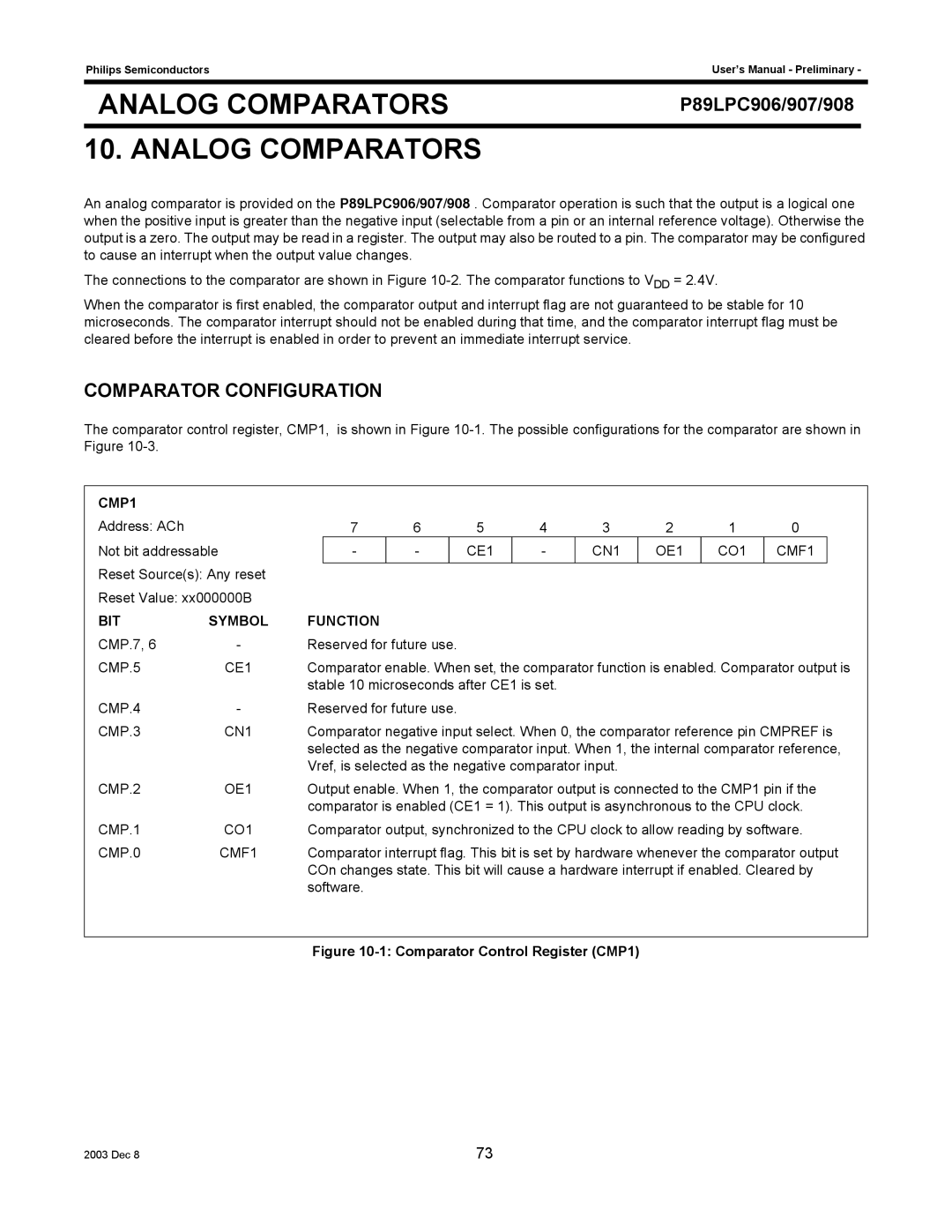
The comparator control register, CMP1, is shown in Figure
CMP1 |
|
|
|
|
|
|
|
|
|
|
|
|
Address: ACh |
| 7 | 6 |
| 5 | 4 | 3 | 2 | 1 | 0 |
| |
Not bit addressable |
| - | - |
| CE1 | - | CN1 | OE1 | CO1 | CMF1 |
| |
Reset Source(s): Any reset |
|
|
|
|
|
|
|
|
|
|
| |
|
|
|
|
|
|
|
|
|
|
| ||
Reset Value: xx000000B |
|
|
|
|
|
|
|
|
|
|
| |
BIT | SYMBOL | FUNCTION |
|
|
|
|
|
|
|
|
| |
CMP.7, 6 | - | Reserved for future use. |
|
|
|
|
|
|
| |||
CMP.5 | CE1 | Comparator enable. When set, the comparator function is enabled. Comparator output is | ||||||||||
|
| stable 10 microseconds after CE1 is set. |
|
|
|
|
| |||||
CMP.4 | - | Reserved for future use. |
|
|
|
|
|
|
| |||
CMP.3 | CN1 | Comparator negative input select. When 0, the comparator reference pin CMPREF is | ||||||||||
|
| selected as the negative comparator input. When 1, the internal comparator reference, | ||||||||||
|
| Vref, is selected as the negative comparator input. |
|
|
|
| ||||||
CMP.2 | OE1 | Output enable. When 1, the comparator output is connected to the CMP1 pin if the | ||||||||||
|
| comparator is enabled (CE1 = 1). This output is asynchronous to the CPU clock. | ||||||||||
CMP.1 | CO1 | Comparator output, synchronized to the CPU clock to allow reading by software. | ||||||||||
CMP.0 | CMF1 | Comparator interrupt flag. This bit is set by hardware whenever the comparator output | ||||||||||
|
| COn changes state. This bit will cause a hardware interrupt if enabled. Cleared by | ||||||||||
|
| software. |
|
|
|
|
|
|
|
|
| |
Figure 10-1: Comparator Control Register (CMP1)
2003 Dec 8 | 73 |