Philips Semiconductors | User’s Manual - Preliminary - | |
|
|
|
TIMERS 0 AND 1 | P89LPC906/907/908 | |
5. TIMERS 0 AND 1 |
|
|
The P89LPC906/907/908 has two
In the “Timer” function, the timer is incremented every PCLK.
In the “Counter” function, the Timer 0 register is incremented in response to a
The “Timer” or “Counter” function is selected by control bit T0C/T in the Special Function Register TMOD. Timer 0 and Timer 1 of the P89LPC906 and P89LPC908, and Timer 1 of the P89LPC907 have four operating modes (modes 0, 1, 2, and 3), which are selected by
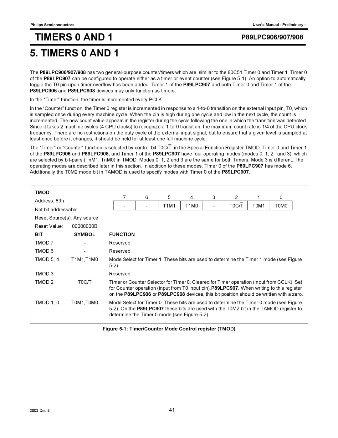
TMOD |
|
|
| 7 | 6 | 5 | 4 |
| 3 | 2 |
|
| 1 | 0 |
| |
Address: 89h |
|
|
|
|
|
|
| |||||||||
|
|
|
| - | - | T1M1 | T1M0 |
| - | T0C/T |
|
| T0M1 | T0M0 |
| |
Not bit addressable |
|
|
|
|
| |||||||||||
|
|
|
|
|
|
|
|
|
|
|
|
| ||||
|
|
|
|
|
|
|
|
|
|
|
|
| ||||
Reset Source(s): Any source |
|
|
|
|
|
|
|
|
|
|
|
|
| |||
Reset Value: | 00000000B |
|
|
|
|
|
|
|
|
|
|
|
|
| ||
BIT | SYMBOL | FUNCTION |
|
|
|
|
|
|
|
|
|
|
| |||
TMOD.7 | - |
|
| Reserved. |
|
|
|
|
|
|
|
|
|
|
| |
TMOD.6 | - |
|
| Reserved. |
|
|
|
|
|
|
|
|
|
|
| |
TMOD.5, 4 | T1M1,T1M0 | Mode Select for Timer 1. These bits are used to determine the Timer 1 mode (see Figure | ||||||||||||||
|
|
|
|
|
|
|
|
|
|
|
|
|
|
| ||
TMOD.3 | - |
|
| Reserved. |
|
|
|
|
|
|
|
|
|
|
| |
TMOD.2 | T0C/T |
|
| Timer or Counter Selector for Timer 0. Cleared for Timer operation (input from CCLK). Set | ||||||||||||
| ||||||||||||||||
|
|
|
| for Counter operation (input from T0 input pin).P89LPC907. When writing to this register | ||||||||||||
|
|
|
| on the P89LPC906 or P89LPC908 devices, this bit position should be written with a zero. | ||||||||||||
TMOD.1, 0 | T0M1,T0M0 | Mode Select for Timer 0. These bits are used to determine the Timer 0 mode (see Figure | ||||||||||||||
|
|
|
| |||||||||||||
|
|
|
| determine the Timer 0 mode (see Figure |
|
|
|
|
|
|
| |||||
Figure 5-1: Timer/Counter Mode Control register (TMOD)
2003 Dec 8 | 41 |