Philips Semiconductors |
|
|
|
|
| User’s Manual - Preliminary - | ||
|
|
|
|
|
|
|
|
|
POWER MONITORING FUNCTIONS | P89LPC906/907/908 | |||||||
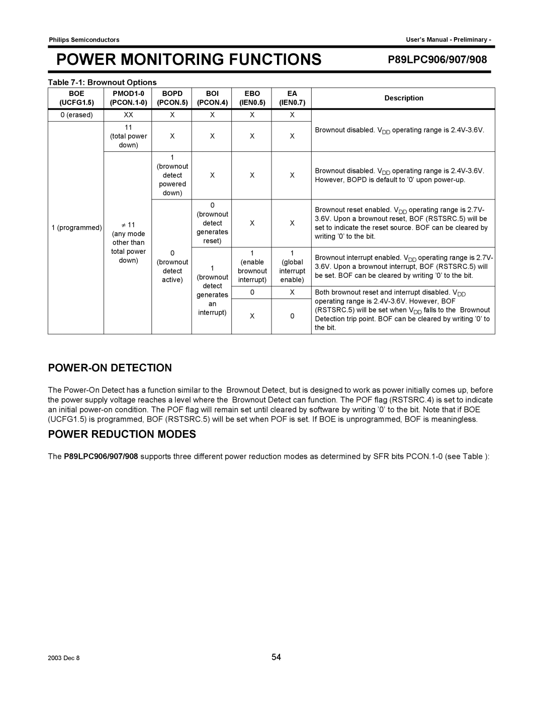
Table |
|
|
|
|
|
| ||
BOE | BOPD | BOI | EBO | EA |
| Description | ||
(UCFG1.5) | (PCON.5) | (PCON.4) | (IEN0.5) | (IEN0.7) |
| |||
|
|
| ||||||
0 (erased) | XX | X | X | X | X |
|
|
|
|
|
|
|
|
|
|
|
|
| 11 |
|
|
|
| Brownout disabled. VDD operating range is | ||
| (total power | X | X | X | X | |||
|
|
|
| |||||
| down) |
|
|
|
|
|
|
|
|
|
|
|
|
|
|
|
|
|
| 1 |
|
|
|
|
|
|
|
| (brownout | X | X | X | Brownout disabled. VDD operating range is | ||
|
| detect | ||||||
|
| powered |
|
|
| However, BOPD is default to ’0’ upon | ||
|
|
|
|
|
|
|
| |
|
| down) |
|
|
|
|
|
|
|
|
|
|
|
|
|
|
|
|
|
| 0 |
|
| Brownout reset enabled. VDD operating range is 2.7V- | ||
|
|
| (brownout |
|
| |||
| ≠ 11 |
| detect | X | X | 3.6V. Upon a brownout reset, BOF (RSTSRC.5) will be | ||
1 (programmed) |
| set to indicate the reset source. BOF can be cleared by | ||||||
(any mode |
| generates |
|
| ||||
|
|
|
| writing ’0’ to the bit. |
|
| ||
| other than |
| reset) |
|
|
|
| |
|
|
|
|
|
|
| ||
| total power | 0 |
| 1 | 1 | Brownout interrupt enabled. VDD operating range is 2.7V- | ||
| down) | (brownout | 1 | (enable | (global | |||
|
| detect | brownout | interrupt | 3.6V. Upon a brownout interrupt, BOF (RSTSRC.5) will | |||
|
| (brownout | be set. BOF can be cleared by writing ’0’ to the bit. | |||||
|
| active) | interrupt) | enable) | ||||
|
| detect |
|
|
| |||
|
|
|
|
|
|
|
| |
|
|
| 0 | X | Both brownout reset and interrupt disabled. VDD | |||
|
|
| generates | |||||
|
|
| an |
|
| operating range is | ||
|
|
|
|
| (RSTSRC.5) will be set when VDD falls to the Brownout | |||
|
|
| interrupt) | X | 0 | |||
|
|
|
| Detection trip point. BOF can be cleared by writing ’0’ to | ||||
|
|
|
|
|
| |||
|
|
|
|
|
| the bit. |
|
|
|
|
|
|
|
|
|
|
|
POWER-ON DETECTION
The
POWER REDUCTION MODES
The P89LPC906/907/908 supports three different power reduction modes as determined by SFR bits
2003 Dec 8 | 54 |