Philips Semiconductors | User’s Manual - Preliminary - | |
|
|
|
POWER MONITORING FUNCTIONS | P89LPC906/907/908 |
|
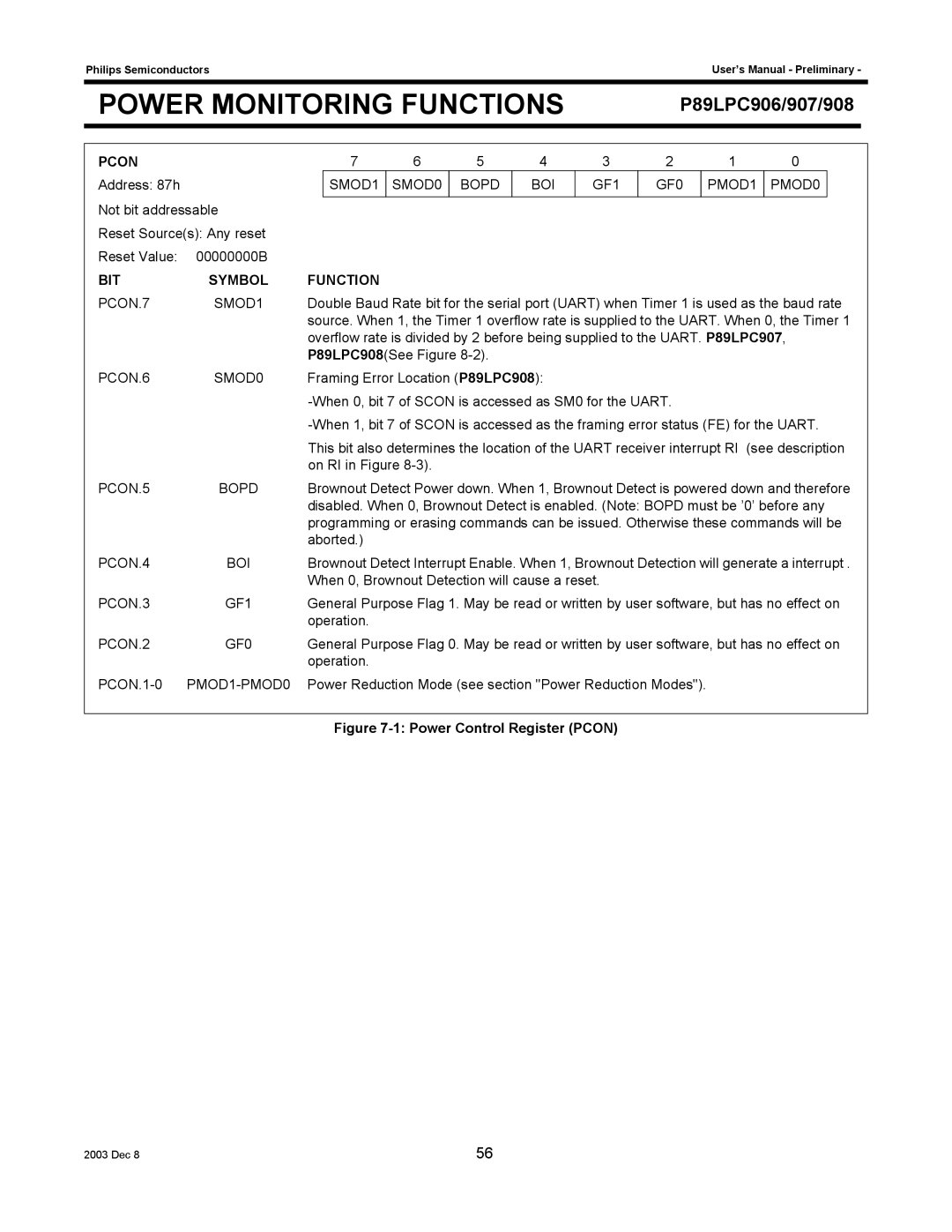
PCON
Address: 87h
Not bit addressable
Reset Source(s): Any reset
Reset Value: 00000000B
7 | 6 | 5 | 4 | 3 | 2 | 1 | 0 |
SMOD1 | SMOD0 | BOPD | BOI | GF1 | GF0 | PMOD1 | PMOD0 |
|
|
|
|
|
|
|
|
BIT | SYMBOL | FUNCTION |
PCON.7 | SMOD1 | Double Baud Rate bit for the serial port (UART) when Timer 1 is used as the baud rate |
|
| source. When 1, the Timer 1 overflow rate is supplied to the UART. When 0, the Timer 1 |
|
| overflow rate is divided by 2 before being supplied to the UART. P89LPC907, |
|
| P89LPC908(See Figure |
PCON.6 | SMOD0 | Framing Error Location (P89LPC908): |
|
| |
|
| |
|
| This bit also determines the location of the UART receiver interrupt RI (see description |
|
| on RI in Figure |
PCON.5 | BOPD | Brownout Detect Power down. When 1, Brownout Detect is powered down and therefore |
|
| disabled. When 0, Brownout Detect is enabled. (Note: BOPD must be ’0’ before any |
|
| programming or erasing commands can be issued. Otherwise these commands will be |
|
| aborted.) |
PCON.4 | BOI | Brownout Detect Interrupt Enable. When 1, Brownout Detection will generate a interrupt . |
|
| When 0, Brownout Detection will cause a reset. |
PCON.3 | GF1 | General Purpose Flag 1. May be read or written by user software, but has no effect on |
|
| operation. |
PCON.2 | GF0 | General Purpose Flag 0. May be read or written by user software, but has no effect on |
|
| operation. |
| Power Reduction Mode (see section "Power Reduction Modes"). | |
|
|
|
|
| Figure |
2003 Dec 8 | 56 |