Philips Semiconductors |
| User’s Manual - Preliminary - | |||
|
|
| |||
POWER MONITORING FUNCTIONS | P89LPC906/907/908 | ||||
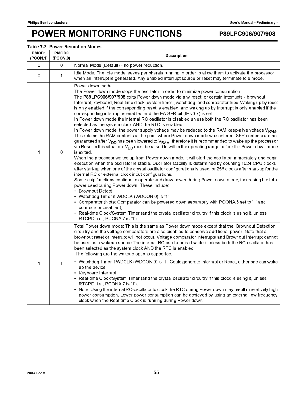
Table |
|
| |||
PMOD1 | PMOD0 | Description |
|
| |
(PCON.1) | (PCON.0) |
|
| ||
|
|
| |||
0 | 0 | Normal Mode (Default) - no power reduction. |
|
| |
|
|
| |||
0 | 1 | Idle Mode. The Idle mode leaves peripherals running in order to allow them to activate the processor | |||
when an interrupt is generated. Any enabled interrupt source or reset may terminate Idle mode. | |||||
|
| ||||
|
| Power down mode: |
|
| |
|
| The Power down mode stops the oscillator in order to minimize power consumption. | |||
|
| The P89LPC906/907/908 exits Power down mode via any reset, or certain interrupts - brownout | |||
|
| Interrupt, keyboard, | |||
|
| is only enabled if the corresponding reset is enabled, and waking up by interrupt is only enabled if the | |||
|
| corresponding interrupt is enabled and the EA SFR bit (IEN0.7) is set. |
|
| |
|
| In Power down mode the internal RC oscillator is disabled unless both the RC oscillator has been | |||
|
| selected as the system clock AND the RTC is enabled |
|
| |
|
| In Power down mode, the power supply voltage may be reduced to the RAM | |||
|
| This retains the RAM contents at the point where Power down mode was entered. SFR contents are not | |||
|
| guaranteed after VDD has been lowered to VRAM, therefore it is recommended to wake up the processor | |||
1 | 0 | via Reset in this situation. VDD must be raised to within the operating range before the Power down mode | |||
is exited. |
|
| |||
|
| When the processor wakes up from Power down mode, it will start the oscillator immediately and begin | |||
|
| execution when the oscillator is stable. Oscillator stability is determined by counting 1024 CPU clocks | |||
|
| after | |||
|
| internal RC or external clock input configurations. |
|
| |
|
| Some chip functions continue to operate and draw power during Power down mode, increasing the total | |||
|
| power used during Power down. These include: |
|
| |
•Brownout Detect
•Watchdog Timer if WDCLK (WDCON.0) is ’1’.
•Comparator (Note: Comparator can be powered down separately with PCONA.5 set to ’1’ and comparator disabled);
•
|
| Total Power down mode: This is the same as Power down mode except that the Brownout Detection |
|
| circuitry and the voltage comparators are also disabled to conserve additional power. Note that a |
|
| brownout reset or interrupt will not occur. Voltage comparator interrupts and Brownout interrupt cannot |
|
| be used as a wakeup source.The internal RC oscillator is disabled unless both the RC oscillator has |
|
| been selected as the system clock AND the RTC is enabled. |
|
| The following are the wakeup options supported: |
1 | 1 | • Watchdog Timer if WDCLK (WDCON.0) is ’1’. Could generate Interrupt or Reset, either one can wake |
|
| up the device |
•Keyboard Interrupt
•
•Note: Using the internal
2003 Dec 8 | 55 |