Philips Semiconductors | User’s Manual - Preliminary - | |
|
|
|
FLASH PROGRAM MEMORY | P89LPC906/907/908 | |
USER CONFIGURATION BYTES |
|
|
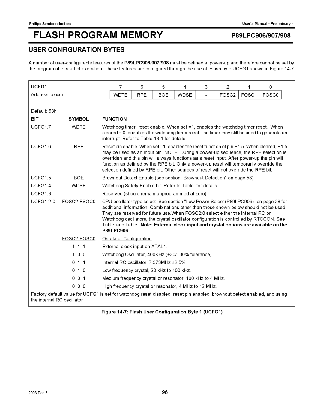
A number of
UCFG1
Address: xxxxh
Default: 63h
7 | 6 | 5 | 4 | 3 | 2 | 1 | 0 |
WDTE | RPE | BOE | WDSE | - | FOSC2 | FOSC1 | FOSC0 |
|
|
|
|
|
|
|
|
BIT | SYMBOL | FUNCTION | ||
UCFG1.7 | WDTE | Watchdog timer reset enable. When set =1, enables the watchdog timer reset. When | ||
|
|
|
| cleared = 0, dusables the watchdog timer reset.The timer may still be used to generate an |
|
|
|
| interrupt. Refer to Table |
UCFG1.6 | RPE | Reset pin enable. When set =1, enables the reset function of pin P1.5. When cleared, P1.5 | ||
|
|
|
| may be used as an input pin. NOTE: During a |
|
|
|
| overriden and this pin will always functions as a reset input. After |
|
|
|
| function as defined by the RPE bit. Only a |
|
|
|
| selection defined by RPE bit. Other sources of reset will not override the RPE bit. |
UCFG1.5 | BOE | Brownout Detect Enable (see section "Brownout Detection" on page 53). | ||
UCFG1.4 | WDSE | Watchdog Safety Enable bit. Refer to Table for details. | ||
UCFG1.3 |
| - |
| Reserved (should remain unprogrammed at zero). |
|
| CPU oscillator type select. See section "Low Power Select (P89LPC906)" on page 28 for | ||
|
|
|
| additional information. Combinations other than those shown below should not be used. |
|
|
|
| They are reserved for future use.When FOSC2:0 select either the internal RC or |
|
|
|
| Watchdog oscillators, the crystal oscillator configuration is controlled by RTCCON. See |
|
|
|
| Table and Table . Note: External clock input and crystal options are available on the |
|
|
|
| P89LPC906. |
|
| Oscillator Configuration | ||
| 1 | 1 | 1 | External clock input on XTAL1. |
| 1 | 0 | 0 | Watchdog Oscillator, 400KHz (+20/ |
| 0 | 1 | 1 | Internal RC oscillator, 7.373MHz ±2.5%. |
| 0 | 1 | 0 | Low frequency crystal, 20 kHz to 100 kHz. |
| 0 | 0 | 1 | Medium frequency crystal or resonator, 100 kHz to 4 MHz. |
| 0 | 0 | 0 | High frequency crystal or resonator, 4 MHz to 12 MHz. |
Factory default value for UCFG1 is set for watchdog reset disabled, reset pin enabled, brownout detect enabled, and using the internal RC oscillator
Figure 14-7: Flash User Configuration Byte 1 (UCFG1)
2003 Dec 8 | 96 |