Philips Semiconductors |
|
|
|
|
|
|
|
| User’s Manual - Preliminary - | |
WATCHDOG TIMER |
|
|
|
|
| P89LPC906/907/908 | ||||
Watchdog |
|
|
|
|
|
|
|
|
| |
Oscillator | ÷32 | ÷2 | ÷2 |
| ÷2 | ÷2 | ÷2 | ÷2 | ÷2 | |
| PCLK |
|
|
|
|
|
|
|
|
|
|
| ÷32 | ÷64 | ÷128 | ÷256 | ÷512 | ÷1024 | ÷2048 |
| ÷4096 |
| WDCLK after a |
|
|
|
|
|
|
|
|
|
| watchdog feed |
|
|
|
|
|
|
|
|
|
| sequence |
|
|
|
|
|
|
|
| TO |
|
|
|
|
|
|
|
|
|
| |
|
|
|
|
|
|
|
|
|
| WATCHDOG |
|
| 000 |
|
|
|
|
|
|
| DOWN |
|
|
|
|
|
|
|
|
| COUNTER | |
|
| 001 |
|
|
|
|
|
|
| |
|
|
|
|
|
|
|
|
| (after one | |
|
| 010 |
|
|
|
|
|
|
| |
PRE2 |
|
|
|
|
|
|
|
| prescaler | |
| 011 |
|
|
|
|
|
|
| ||
| DECODE |
|
|
|
|
|
|
| count delay | |
PRE1 | 100 |
|
|
|
|
|
|
|
| |
| 101 |
|
|
|
|
|
|
|
| |
PRE0 |
| 110 |
|
|
|
|
|
|
|
|
| 111 |
|
|
|
|
|
|
|
| |
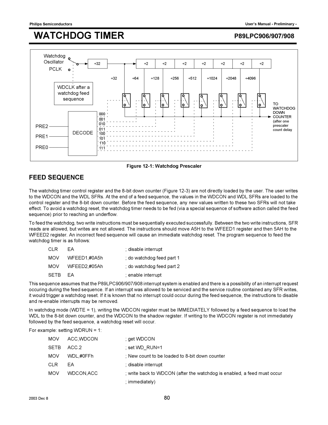
Figure 12-1: Watchdog Prescaler
FEED SEQUENCE
The watchdog timer control register and the
To feed the watchdog, two write instructions must be sequentially executed successfully. Between the two write instructions, SFR reads are allowed, but writes are not allowed. The instructions should move A5H to the WFEED1 register and then 5AH to the WFEED2 register. An incorrect feed sequence will cause an immediate watchdog reset. The program sequence to feed the watchdog timer is as follows:
CLR | EA | ; disable interrupt |
MOV | WFEED1,#0A5h | ; do watchdog feed part 1 |
MOV | WFEED2,#05Ah | ; do watchdog feed part 2 |
SETB | EA | ; enable interrupt |
This sequence assumes that the P89LPC906/907/908 interrupt system is enabled and there is a possibility of an interrupt request occuring during the feed sequence. If an interrupt was allowed to be serviced and the service routine contained any SFR writes, it would trigger a watchdog reset. If it is known that no interrupt could occur during the feed sequence, the instructions to disable and
In watchdog mode (WDTE = 1), writing the WDCON register must be IMMEDIATELY followed by a feed sequence to load the WDL to the
For example: setting WDRUN = 1:
MOV | ACC,WDCON | ; get WDCON |
SETB | ACC.2 | ; set WD_RUN=1 |
MOV | WDL,#0FFh | ; New count to be loaded to |
CLR | EA | ; disable interrupt |
MOV | WDCON,ACC | ; write back to WDCON (after the watchdog is enabled, a feed must occur |
|
| ; immediately) |
2003 Dec 8 | 80 |