Philips Semiconductors |
|
|
|
|
|
|
|
| User’s Manual - Preliminary - | ||||
|
|
|
|
|
|
|
|
|
|
|
| ||
TIMERS 0 AND 1 |
|
|
|
|
| P89LPC906/907/908 | |||||||
|
|
|
|
|
|
|
|
|
|
| |||
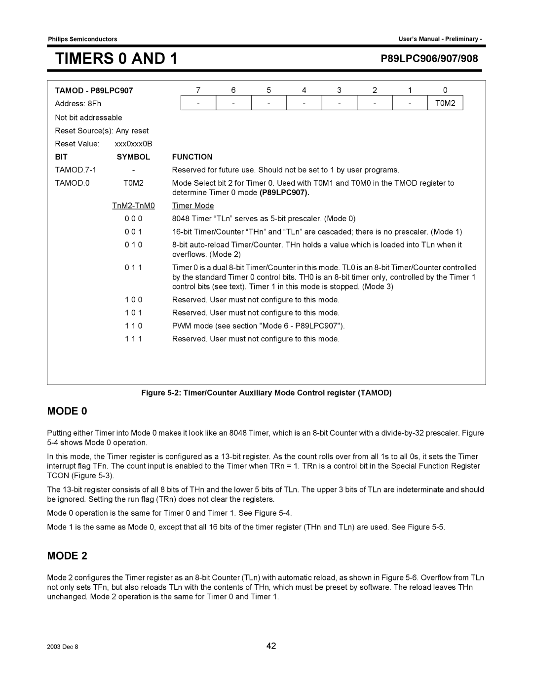
TAMOD - P89LPC907 | 7 | 6 | 5 | 4 | 3 | 2 | 1 | 0 |
|
| |||
Address: 8Fh |
|
| - | - | - | - | - | - |
| - | T0M2 |
| |
Not bit addressable |
|
|
|
|
|
|
|
|
|
|
|
| |
Reset Source(s): Any reset |
|
|
|
|
|
|
|
|
|
|
|
| |
Reset Value: | xxx0xxx0B |
|
|
|
|
|
|
|
|
|
|
|
|
BIT | SYMBOL | FUNCTION |
|
|
|
|
|
|
|
|
|
| |
| - | Reserved for future use. Should not be set to 1 by user programs. |
|
|
| ||||||||
TAMOD.0 | T0M2 | Mode Select bit 2 for Timer 0. Used with T0M1 and T0M0 in the TMOD register to | |||||||||||
|
| determine Timer 0 mode (P89LPC907). |
|
|
|
|
|
|
| ||||
| Timer Mode |
|
|
|
|
|
|
|
|
|
| ||
| 0 0 0 | 8048 Timer “TLn” serves as |
|
|
|
|
|
| |||||
| 0 0 1 | ||||||||||||
| 0 1 0 | ||||||||||||
|
| overflows. (Mode 2) |
|
|
|
|
|
|
|
|
| ||
| 0 1 1 | Timer 0 is a dual | |||||||||||
|
| by the standard Timer 0 control bits. TH0 is an | |||||||||||
|
| control bits (see text). Timer 1 in this mode is stopped. (Mode 3) |
|
|
| ||||||||
| 1 0 0 | Reserved. User must not configure to this mode. |
|
|
|
|
|
| |||||
| 1 0 1 | Reserved. User must not configure to this mode. |
|
|
|
|
|
| |||||
| 1 1 0 | PWM mode (see section "Mode 6 - P89LPC907"). |
|
|
|
|
|
| |||||
| 1 1 1 | Reserved. User must not configure to this mode. |
|
|
|
|
|
| |||||
|
|
|
|
|
|
|
|
|
|
|
|
|
|
Figure 5-2: Timer/Counter Auxiliary Mode Control register (TAMOD)
MODE 0
Putting either Timer into Mode 0 makes it look like an 8048 Timer, which is an
In this mode, the Timer register is configured as a
The
Mode 0 operation is the same for Timer 0 and Timer 1. See Figure
Mode 1 is the same as Mode 0, except that all 16 bits of the timer register (THn and TLn) are used. See Figure
MODE 2
Mode 2 configures the Timer register as an
2003 Dec 8 | 42 |