Philips Semiconductors | User’s Manual - Preliminary - | ||
|
|
| |
WATCHDOG TIMER | P89LPC906/907/908 |
| |
MOV | WFEED1,#0A5h | ; do watchdog feed part 1 | |
MOV | WFEED2,#05Ah | ; do watchdog feed part 2 | |
SETB | EA | ; enable interrupt | |
In timer mode (WDTE = 0), WDCON is loaded to the control register every CCLK cycle (no feed sequence is required to load the control register), but a feed sequence is required to load from the WDL SFR to the
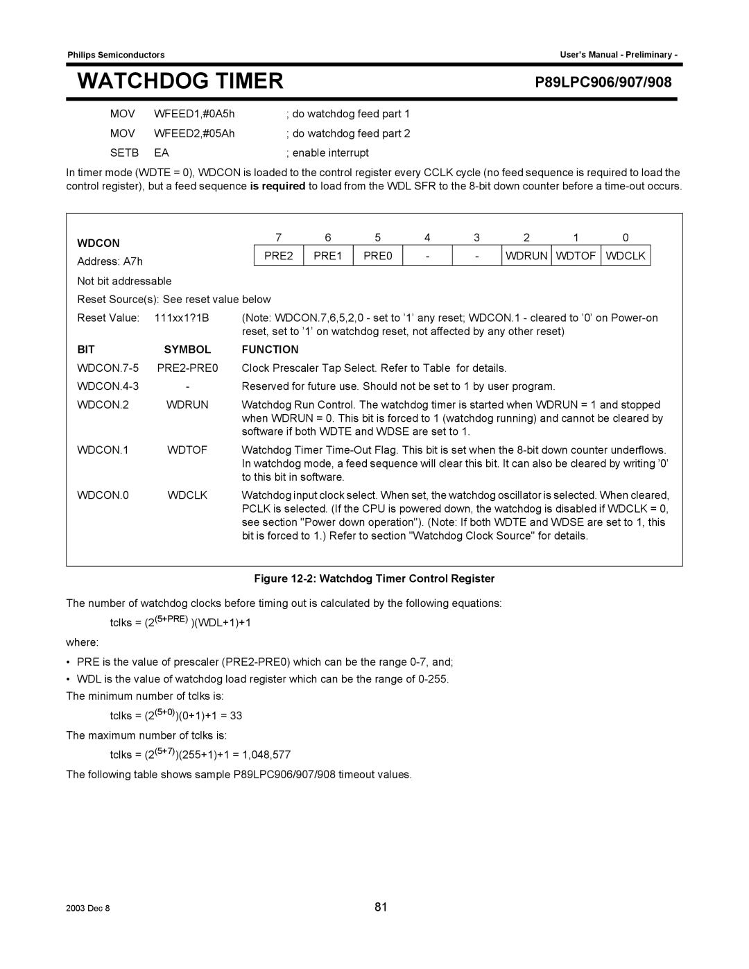
WDCON |
| 7 | 6 | 5 | 4 |
| 3 | 2 |
| 1 | 0 |
| |
|
| PRE2 | PRE1 | PRE0 | - |
| - | WDRUN | WDTOF | WDCLK |
| ||
Address: A7h |
|
|
|
| |||||||||
|
|
|
|
|
|
|
|
|
|
|
|
| |
Not bit addressable |
|
|
|
|
|
|
|
|
|
|
|
| |
Reset Source(s): See reset value below |
|
|
|
|
|
|
|
|
|
| |||
Reset Value: | 111xx1?1B | (Note: WDCON.7,6,5,2,0 - set to ’1’ any reset; WDCON.1 - cleared to ’0’ on | |||||||||||
|
| reset, set to ’1’ on watchdog reset, not affected by any other reset) |
|
|
| ||||||||
BIT | SYMBOL | FUNCTION |
|
|
|
|
|
|
|
|
|
| |
| Clock Prescaler Tap Select. Refer to Table for details. |
|
|
| |||||||||
- | Reserved for future use. Should not be set to 1 by user program. |
|
|
| |||||||||
WDCON.2 | WDRUN | Watchdog Run Control. The watchdog timer is started when WDRUN = 1 and stopped | |||||||||||
|
| when WDRUN = 0. This bit is forced to 1 (watchdog running) and cannot be cleared by | |||||||||||
|
| software if both WDTE and WDSE are set to 1. |
|
|
|
|
|
| |||||
WDCON.1 | WDTOF | Watchdog Timer | |||||||||||
|
| In watchdog mode, a feed sequence will clear this bit. It can also be cleared by writing ’0’ | |||||||||||
|
| to this bit in software. |
|
|
|
|
|
|
|
|
| ||
WDCON.0 | WDCLK | Watchdog input clock select. When set, the watchdog oscillator is selected. When cleared, | |||||||||||
|
| PCLK is selected. (If the CPU is powered down, the watchdog is disabled if WDCLK = 0, | |||||||||||
see section "Power down operation"). (Note: If both WDTE and WDSE are set to 1, this bit is forced to 1.) Refer to section "Watchdog Clock Source" for details.
Figure 12-2: Watchdog Timer Control Register
The number of watchdog clocks before timing out is calculated by the following equations: tclks = (2(5+PRE) )(WDL+1)+1
where:
•PRE is the value of prescaler
•WDL is the value of watchdog load register which can be the range of
tclks = (2(5+0))(0+1)+1 = 33 The maximum number of tclks is:
tclks = (2(5+7))(255+1)+1 = 1,048,577
The following table shows sample P89LPC906/907/908 timeout values.
2003 Dec 8 | 81 |