Philips Semiconductors | User’s Manual - Preliminary - | |
|
|
|
TIMERS 0 AND 1 | P89LPC906/907/908 | |
MODE 3 |
|
|
When Timer 1 is in Mode 3 it is stopped. The effect is the same as setting TR1 = 0.
Timer 0 in Mode 3 establishes TL0 and TH0 as two separate
Mode 3 is provided for applications that require an extra
Note: When Timer 0 is in Mode 3, Timer 1 can be turned on and off by switching it into and out of its own Mode 3. It can still be used by the serial port as a baud rate generator (P89LPC907,P89LPC908), or in any application not requiring an interrupt.
MODE 6 - P89LPC907
In this mode, Timer 0 can be changed to a PWM with a full period of 256 timer clocks (see Figure
•TF0 is set and cleared in hardware;
•The low period of the TF0 is in TH0, and should be between 1 and 254, and;
•The high period of the TF0 is always
•Loading TH0 with 00h will force the T0 pin high, loading TH0 with FFh will force the T0 pin low.
Note that an interrupt can still be enabled on the low to high transition of TF0, and that TF0 can still be cleared in software as in any other modes.
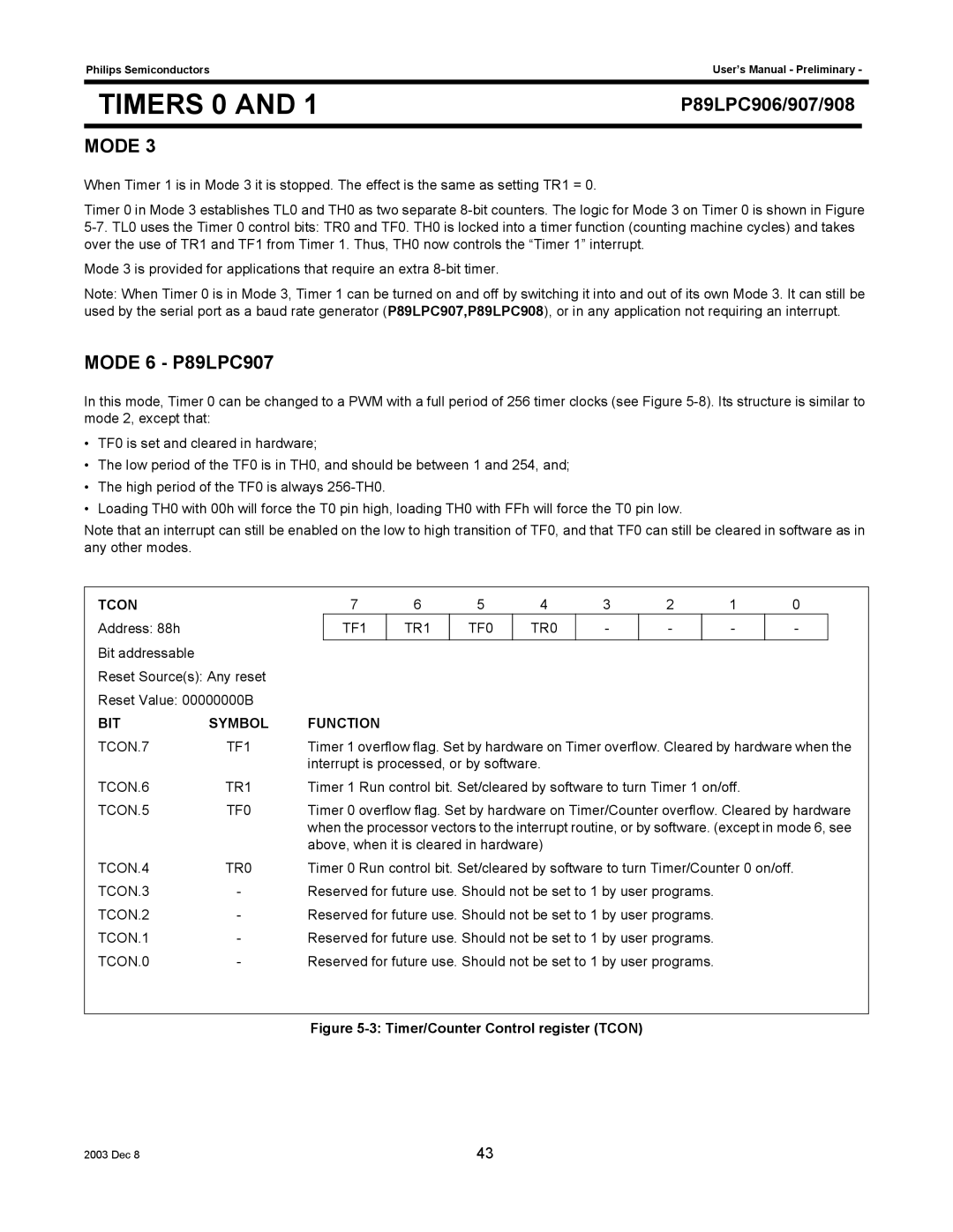
TCON |
| 7 | 6 | 5 | 4 | 3 | 2 |
| 1 | 0 |
| |
Address: 88h |
|
| TF1 | TR1 | TF0 | TR0 | - | - |
| - | - |
|
Bit addressable |
|
|
|
|
|
|
|
|
|
|
|
|
Reset Source(s): Any reset |
|
|
|
|
|
|
|
|
|
|
| |
Reset Value: 00000000B |
|
|
|
|
|
|
|
|
|
|
| |
BIT | SYMBOL | FUNCTION |
|
|
|
|
|
|
|
|
| |
TCON.7 | TF1 | Timer 1 overflow flag. Set by hardware on Timer overflow. Cleared by hardware when the | ||||||||||
|
| interrupt is processed, or by software. |
|
|
|
|
|
| ||||
TCON.6 | TR1 | Timer 1 Run control bit. Set/cleared by software to turn Timer 1 on/off. |
|
| ||||||||
TCON.5 | TF0 | Timer 0 overflow flag. Set by hardware on Timer/Counter overflow. Cleared by hardware | ||||||||||
|
| when the processor vectors to the interrupt routine, or by software. (except in mode 6, see | ||||||||||
|
| above, when it is cleared in hardware) |
|
|
|
|
|
| ||||
TCON.4 | TR0 | Timer 0 Run control bit. Set/cleared by software to turn Timer/Counter 0 on/off. | ||||||||||
TCON.3 | - | Reserved for future use. Should not be set to 1 by user programs. |
|
|
| |||||||
TCON.2 | - | Reserved for future use. Should not be set to 1 by user programs. |
|
|
| |||||||
TCON.1 | - | Reserved for future use. Should not be set to 1 by user programs. |
|
|
| |||||||
TCON.0 | - | Reserved for future use. Should not be set to 1 by user programs. |
|
|
| |||||||
Figure 5-3: Timer/Counter Control register (TCON)
2003 Dec 8 | 43 |