SDIO Simplified Specification Version 2.00 | ©Copyright | ||||
|
| ||||
|
|
|
|
|
|
| SD Memory | SDIO |
| Comment |
|
| Command | Command |
|
|
|
| CMD18, |
| read/write commands. |
|
|
| CMD24, |
|
|
|
|
| CMD25 |
|
|
|
|
Table
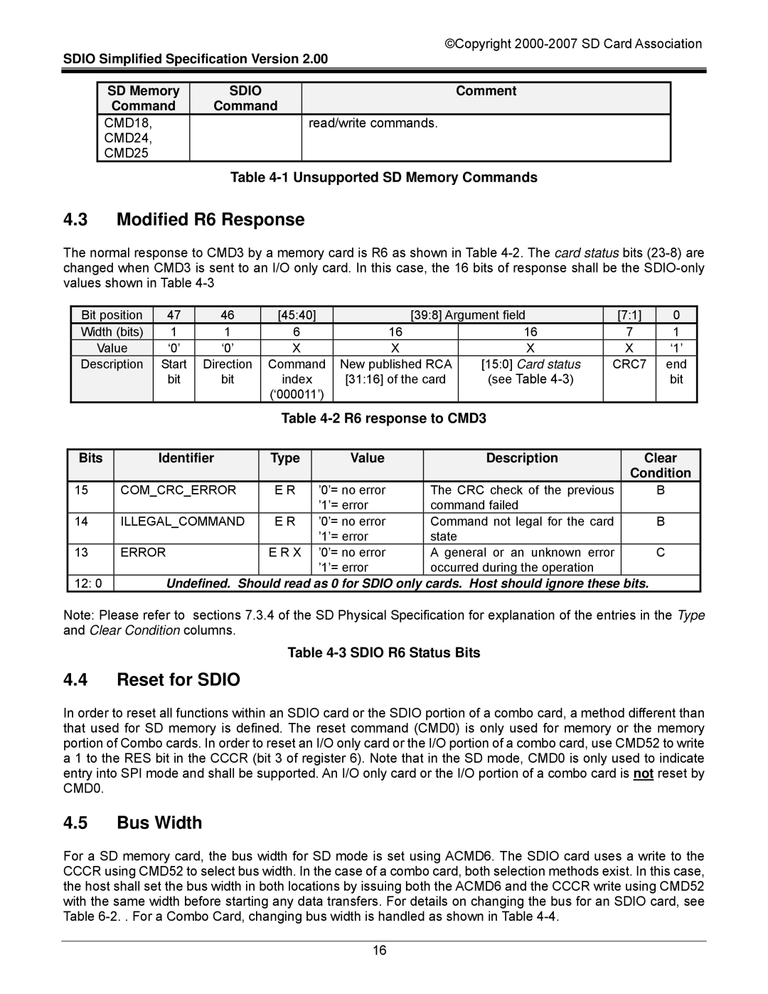
4.3Modified R6 Response
The normal response to CMD3 by a memory card is R6 as shown in Table
| Bit position | 47 | 46 | [45:40] |
|
| [39:8] Argument field |
| [7:1] | 0 |
| |||||
| Width (bits) | 1 | 1 | 6 |
|
| 16 |
|
| 16 |
| 7 | 1 |
| ||
| Value | ‘0’ | ‘0’ | X |
| X |
|
| X |
|
| X | ‘1’ |
| ||
| Description | Start | Direction | Command | New published RCA | [15:0] Card status | CRC7 | end |
| |||||||
|
|
| bit | bit | index |
| [31:16] of the card | (see Table |
|
|
| bit |
| |||
|
|
|
|
| (‘000011’) |
|
|
|
|
|
|
|
|
| ||
|
|
|
|
| Table |
|
|
|
|
| ||||||
|
|
|
|
|
|
|
|
|
|
|
|
|
|
| ||
| Bits |
| Identifier | Type |
|
| Value |
|
| Description |
|
| Clear |
| ||
|
|
|
|
|
|
|
|
|
|
|
|
|
| Condition |
| |
| 15 | COM_CRC_ERROR | E R |
| ’0’= no error |
| The CRC check of the previous |
|
| B |
| |||||
|
|
|
|
|
|
| ’1’= error |
| command failed |
|
|
|
|
| ||
| 14 | ILLEGAL_COMMAND | E R |
| ’0’= no error |
| Command not legal for the card |
|
| B |
| |||||
|
|
|
|
|
|
| ’1’= error |
| state |
|
|
|
|
|
| |
| 13 | ERROR |
| E R X |
| ’0’= no error |
| A general or an unknown error |
|
| C |
| ||||
|
|
|
|
|
|
| ’1’= error |
| occurred during the operation |
|
|
|
|
| ||
| 12: 0 |
| Undefined. Should read as 0 for SDIO only | cards. Host should ignore these bits. |
|
| ||||||||||
Note: Please refer to sections 7.3.4 of the SD Physical Specification for explanation of the entries in the Type and Clear Condition columns.
Table
4.4Reset for SDIO
In order to reset all functions within an SDIO card or the SDIO portion of a combo card, a method different than that used for SD memory is defined. The reset command (CMD0) is only used for memory or the memory portion of Combo cards. In order to reset an I/O only card or the I/O portion of a combo card, use CMD52 to write a 1 to the RES bit in the CCCR (bit 3 of register 6). Note that in the SD mode, CMD0 is only used to indicate entry into SPI mode and shall be supported. An I/O only card or the I/O portion of a combo card is not reset by CMD0.
4.5Bus Width
For a SD memory card, the bus width for SD mode is set using ACMD6. The SDIO card uses a write to the CCCR using CMD52 to select bus width. In the case of a combo card, both selection methods exist. In this case, the host shall set the bus width in both locations by issuing both the ACMD6 and the CCCR write using CMD52 with the same width before starting any data transfers. For details on changing the bus for an SDIO card, see Table
16