SDIO Simplified Specification Version 2.00 |
| ©Copyright | |||
|
|
| |||
|
|
|
|
|
|
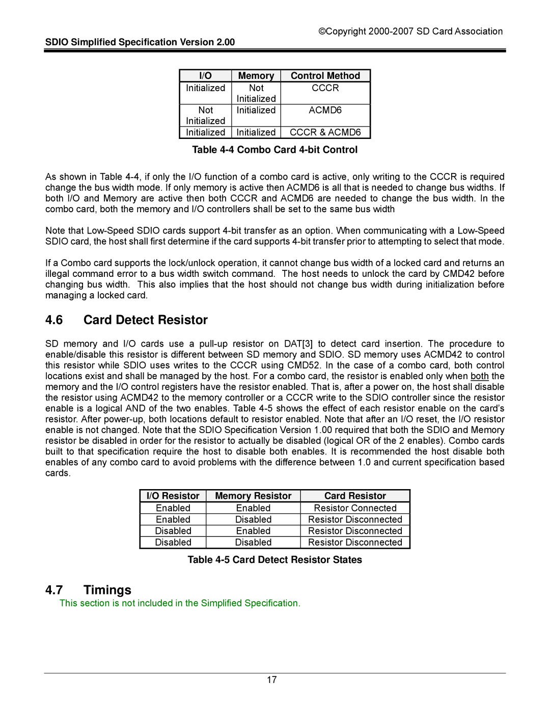
| I/O |
| Memory | Control Method |
|
| Initialized |
| Not | CCCR |
|
|
|
| Initialized |
|
|
| Not |
| Initialized | ACMD6 |
|
| Initialized |
|
|
|
|
| Initialized |
| Initialized | CCCR & ACMD6 |
|
Table 4-4 Combo Card 4-bit Control
As shown in Table
Note that
If a Combo card supports the lock/unlock operation, it cannot change bus width of a locked card and returns an illegal command error to a bus width switch command. The host needs to unlock the card by CMD42 before changing bus width. This also implies that the host should not change bus width during initialization before managing a locked card.
4.6Card Detect Resistor
SD memory and I/O cards use a
I/O Resistor | Memory Resistor |
Enabled | Enabled |
Enabled | Disabled |
Disabled | Enabled |
Disabled | Disabled |
Card Resistor
Resistor Connected
Resistor Disconnected
Resistor Disconnected
Resistor Disconnected
Table 4-5 Card Detect Resistor States
4.7Timings
This section is not included in the Simplified Specification.
17