©Copyright
SDIO Simplified Specification Version 2.00
6.14Bus State Diagram
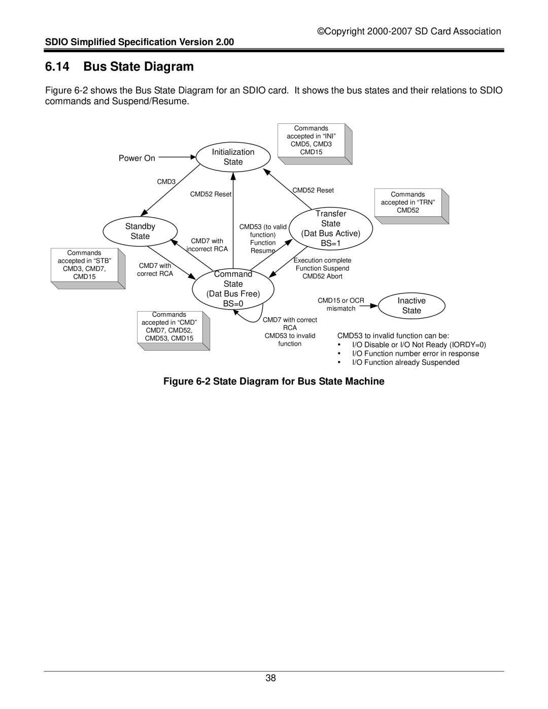
Figure 6-2 shows the Bus State Diagram for an SDIO card. It shows the bus states and their relations to SDIO commands and Suspend/Resume.
Commands
accepted in “STB”
CMD3, CMD7,
CMD15
|
|
|
|
|
|
|
| Commands |
|
|
|
|
|
|
|
|
|
|
|
|
|
| accepted in “INI” |
|
|
|
|
|
|
|
|
|
|
| Initialization |
| CMD5, CMD3 |
|
|
|
|
|
| |
Power On |
|
|
|
| CMD15 |
|
|
|
|
|
| |||
|
|
| State |
|
|
|
|
|
|
| ||||
|
|
|
|
|
|
|
|
|
|
|
| |||
| CMD3 | CMD52 Reset |
|
| CMD52 Reset |
|
|
|
|
|
| |||
|
|
|
|
|
|
|
| |||||||
|
|
|
|
|
|
|
|
|
|
| ||||
|
|
|
|
|
|
|
|
| Commands |
| ||||
|
|
|
|
|
|
|
|
|
|
| ||||
|
|
|
|
|
|
|
|
|
|
|
|
| accepted in “TRN” |
|
|
|
|
|
|
|
|
| Transfer |
| CMD52 |
| |||
Standby |
|
|
| CMD53 (to valid | State |
|
|
| ||||||
State | CMD7 with | function) | (Dat Bus Active) |
|
|
| ||||||||
|
|
| Function | BS=1 |
|
|
| |||||||
|
|
| incorrect RCA | Resume |
|
|
|
|
|
|
| |||
| CMD7 with |
|
|
|
|
| Execution complete |
|
|
| ||||
|
|
|
|
|
| Function Suspend |
|
|
| |||||
correct RCA |
|
| Command |
|
|
| ||||||||
|
| CMD52 Abort |
|
|
| |||||||||
|
|
|
|
| State |
|
|
|
|
|
|
| ||
|
|
|
|
| (Dat Bus Free) | CMD15 or OCR |
| Inactive | ||||||
|
|
|
|
| BS=0 |
| ||||||||
|
|
|
|
| mismatch |
|
| State | ||||||
|
|
|
|
|
|
|
|
| ||||||
| Commands |
|
|
|
|
| ||||||||
|
|
|
| CMD7 with correct |
|
|
|
|
|
| ||||
| accepted in “CMD” |
|
|
|
|
|
|
| ||||||
|
|
| RCA |
|
|
|
|
|
| |||||
| CMD7, CMD52, |
|
| CMD53 to invalid function can be: | ||||||||||
|
| CMD53 to invalid | ||||||||||||
| CMD53, CMD15 |
| ||||||||||||
|
|
| function | y I/O Disable or I/O Not Ready (IORDY=0) | ||||||||||
|
|
|
|
|
|
| ||||||||
y I/O Function number error in response y I/O Function already Suspended
Figure 6-2 State Diagram for Bus State Machine
38
