©Copyright
SDIO Simplified Specification Version 2.00
6.11Card Information Structure (CIS)
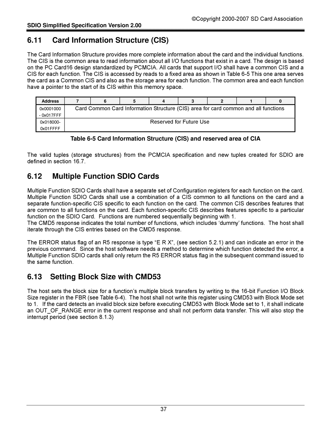
The Card Information Structure provides more complete information about the card and the individual functions. The CIS is the common area to read information about all I/O functions that exist in a card. The design is based on the PC Card16 design standardized by PCMCIA. All cards that support I/O shall have a common CIS and a CIS for each function. The CIS is accessed by reads to a fixed area as shown in Table
Address | 7 | 6 | 5 | 4 | 3 |
| 2 | 1 | 0 |
0x0001000 | Card | Common Card Information Structure (CIS) area for card common and all functions | |||||||
- 0x017FFF |
|
|
|
|
|
|
|
|
|
0x018000- |
|
|
| Reserved for Future Use |
|
|
| ||
0x01FFFF |
|
|
|
|
|
|
|
|
|
Table 6-5 Card Information Structure (CIS) and reserved area of CIA
The valid tuples (storage structures) from the PCMCIA specification and new tuples created for SDIO are defined in section 16.7.
6.12Multiple Function SDIO Cards
Multiple Function SDIO Cards shall have a separate set of Configuration registers for each function on the card. Multiple Function SDIO Cards shall use a combination of a CIS common to all functions on the card and a separate
The CMD5 response indicates the total number of functions, which includes ‘dummy’ functions. The host shall iterate through the CIS entries based on the CMD5 response.
The ERROR status flag of an R5 response is type “E R X”, (see section 5.2.1) and can indicate an error in the previous command. Since the host software needs a method to determine which function detected the error, a Multiple Function SDIO cards shall only return the R5 ERROR status flag in the subsequent command issued to the same function.
6.13Setting Block Size with CMD53
The host sets the block size for a function’s multiple block transfers by writing to the
37