©Copyright
SDIO Simplified Specification Version 2.00
Field | Type | Description |
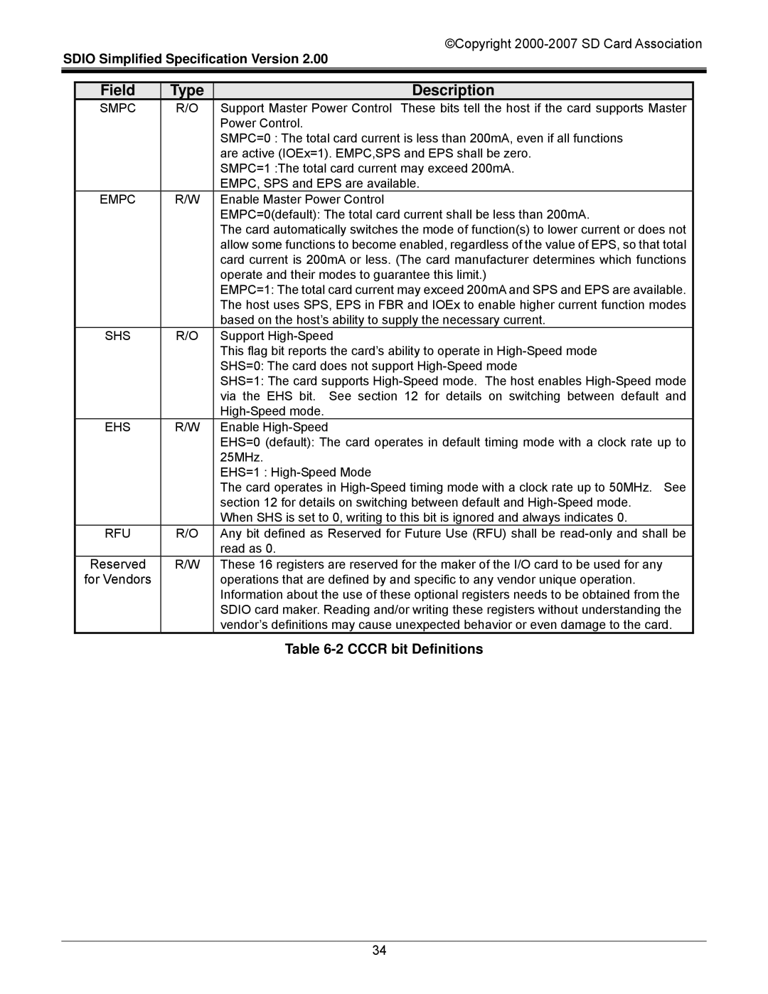
SMPC | R/O | Support Master Power Control These bits tell the host if the card supports Master |
|
| Power Control. |
|
| SMPC=0 : The total card current is less than 200mA, even if all functions |
|
| are active (IOEx=1). EMPC,SPS and EPS shall be zero. |
|
| SMPC=1 :The total card current may exceed 200mA. |
|
| EMPC, SPS and EPS are available. |
EMPC | R/W | Enable Master Power Control |
|
| EMPC=0(default): The total card current shall be less than 200mA. |
|
| The card automatically switches the mode of function(s) to lower current or does not |
|
| allow some functions to become enabled, regardless of the value of EPS, so that total |
|
| card current is 200mA or less. (The card manufacturer determines which functions |
|
| operate and their modes to guarantee this limit.) |
|
| EMPC=1: The total card current may exceed 200mA and SPS and EPS are available. |
|
| The host uses SPS, EPS in FBR and IOEx to enable higher current function modes |
|
| based on the host’s ability to supply the necessary current. |
SHS | R/O | Support |
|
| This flag bit reports the card’s ability to operate in |
|
| SHS=0: The card does not support |
|
| SHS=1: The card supports |
|
| via the EHS bit. See section 12 for details on switching between default and |
|
| |
EHS | R/W | Enable |
|
| EHS=0 (default): The card operates in default timing mode with a clock rate up to |
|
| 25MHz. |
|
| EHS=1 : |
|
| The card operates in |
|
| section 12 for details on switching between default and |
|
| When SHS is set to 0, writing to this bit is ignored and always indicates 0. |
RFU | R/O | Any bit defined as Reserved for Future Use (RFU) shall be |
|
| read as 0. |
Reserved | R/W | These 16 registers are reserved for the maker of the I/O card to be used for any |
for Vendors |
| operations that are defined by and specific to any vendor unique operation. |
|
| Information about the use of these optional registers needs to be obtained from the |
|
| SDIO card maker. Reading and/or writing these registers without understanding the |
|
| vendor’s definitions may cause unexpected behavior or even damage to the card. |
|
| Table |
34