©Copyright
SDIO Simplified Specification Version 2.00
address that increment by 1 after each operation. This command is used when large amounts of I/O data exist within the I/O card in a RAM like data buffer. In this operation, the start address is loaded into the Register Address field. The first operation occurs at that address within the I/O card. The next operation shall occur at address+1 with the address incrementing by 1 until the operation has completed. As with OP Code 0, the number of bytes is set in the Byte Count field of the command.
Register Address: | Start Address of I/O register to read or write. Range is [0x1FFFF:0] | |||||
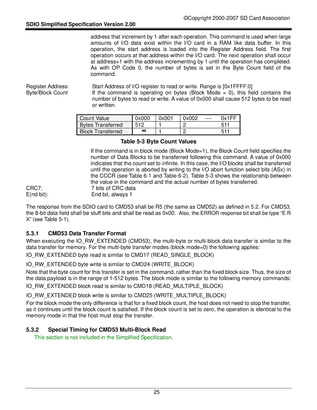
Byte/Block Count | If the command is operating on bytes (Block Mode = 0), this field contains the | |||||
| number of bytes to read or write. A value of 0x000 shall cause 512 bytes to be read | |||||
| or written. |
|
|
|
|
|
|
|
|
|
|
|
|
| Count Value | 0x000 | 0x001 | 0x002 | 0x1FF |
|
| Bytes Transferred | 512 | 1 | 2 | 511 |
|
| Block Transferred | ∞ | 1 | 2 | 511 |
|
| Table |
|
| |||
| If the command is in block mode (Block Mode=1), the Block Count field specifies the | |||||
| number of Data Blocks to be transferred following this command. A value of 0x000 | |||||
| indicates that the count set to infinite. In this case, the I/O blocks shall be transferred | |||||
| until the operation is aborted by writing to the I/O abort function select bits (ASx) in | |||||
| the CCCR (see Table | |||||
| the value in the command and the actual number of bytes transferred. | |||||
CRC7: | 7 bits of CRC data |
|
|
|
| |
E(nd bit): | End bit, always 1 |
|
|
|
|
|
The response from the SDIO card to CMD53 shall be R5 (the same as CMD52) as defined in 5.2. For CMD53, the
5.3.1CMD53 Data Transfer Format
When executing the IO_RW_EXTENDED (CMD53), the
IO_RW_EXTENDED byte read is similar to CMD17 (READ_SINGLE_BLOCK)
IO_RW_EXTENDED byte write is similar to CMD24 (WRITE_BLOCK)
Note that the byte count for this transfer is set in the command, rather than the fixed block size. Thus, the size of the data payload is in the range of
IO_RW_EXTENDED block read is similar to CMD18 (READ_MULTIPLE_BLOCK)
IO_RW_EXTENDED block write is similar to CMD25 (WRITE_MULTIPLE_BLOCK)
For the block mode the only difference is that for a fixed block count, the host does not need to stop the transfer, as it continues until the block count is satisfied. If the block count is set to zero, the operation is identical to the memory mode in that the host must stop the transfer.
5.3.2Special Timing for CMD53
25