NOTE: The upper and lower blade guides support the blade and keep it from twisting during operation. An adjustment is necessary when blades are changed or replaced.
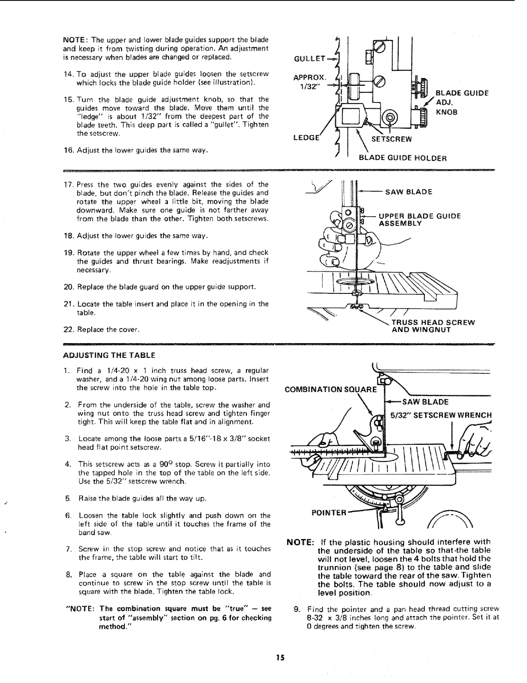
14.To adjust the upper blade guides loosen the setscrew which locks the blade guide holder (see illustration).
!5. Turn the blade guide adjustment knob, so that the guides move toward the blade, Move them until the "ledge" is about 1/32" from the deepest part of the
blade teeth. This deep part is called a "gullet". Tighten the setscrew.
16.Adjust the lower guides the same way.
17.Press the two guides evenly against the sides of the blade, but don't pinch the blade. Release the guides and rotate the upper wheel a little bit, moving the blade
downward. Make sure one guide is not farther away from the blade than the other. Tighten both setscrews.
18.Adjust the lower guides the same way.
19.Rotate the upper wheel a few times by hand, and check
the guides and thrust bearings. Make readjustments if necessary.
20.Replace the blade guard on the upper guide support_
21.Locate the table insert and place it in the opening in the table.
22.Replace the cover.
ADJUSTING THE TABLE
1.Find a
2.From the underside of the table, screw the washer and
wing nut onto the truss head screw and tighten finger tight. This will keep the table flat and in alignment.
3.Locate among the loose parts a
4.This setscrew acts as a 90 ° stop. Screw it partially into the tapped hole in the top of the table on the left side. Use the 5/32" setscrew wrench.
5.Raise the blade guides all the way up.
6.Loosen the table lock slightly and push down on the left side of the table until it touches the frame of the band saw.
7.Screw in the stop screw and notice that as it touches the frame, the table will start to tilt.
8, Place a square on the table against the blade and continue to screw in the stop screw until the table is square with the blade. Tighten "the table lock.
"NOTE: The combination square must be "true"
start of "assembly" section on pg. 6 for checking method,"
APPROX.
1/32"'
BLADE GUIDE
KNOB
SETSCREW
BLADE GUIDE HOLDER
v__>/
SAW BLADE
"_ UPPER BLADE GUIDE
TRUSS HEAD SCREW
AND WINGNUT
COMBINATION SQUARE
5/32" SETSCREW WRENCH
NOTE: If the plastic housing should interfere with the underside of the table so that4he table will not level, loosen the 4 boltsthat hold the trunnion (see page 8) to the table and slide the table toward the rear of the saw. Tighten the bolts. The table should now adjust to a level position.
9.Find the pointer and a pan head thread cutting screw
15