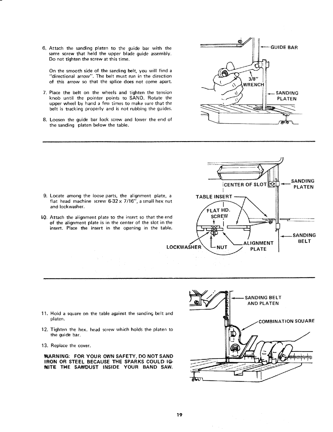
6, Attach the sanding platen to the guide bar with the same screw that held the upper blade guide assembly. Do not tighten the screw at this time.
On the smooth side of the sanding belt, you will find a
"directional arrow". The belt must run in the direction of this arrow so that the splice does not come apart,
7. Place | the belt | on the | wheels | and | tighten |
| the | tension | 3 | |
knob | until | the | pointer | points | to | SAND. | Rotate the | PLATEN | ||
upper | wheel | by | hand a | few times to make | sure that the |
| ||||
belt | is tracking | properly | and | is not | rubbing | the | guides. |
| ||
8, Loosen the guide bar lock screw and lower the end of the sanding platen below the table.
|
|
|
|
|
|
| ¢ |
|
|
|
|
|
|
| ICENTER OF SLOT |
|
|
|
|
|
|
| I |
9. Locate among the | loose | parts, | the alignment | plate, | a | TABLE iNSERT | |
flat | head machine | screw | x 7/16", a small | hex | nut |
| |
and | Iockwasher. |
|
|
|
|
|
|
SANDING
PLATEN
_0, Attach | the alignment | plate | to the insert | so that | the | end |
| / | SCREW | / | ||||
of the | alignment | plate | is | in | the | center of | the | slot | in | the |
| [ | _ i |
|
insert. | Place the | insert | in | the | opening | in | the | table. | __[:::::::_ |
| ;ANDING | |||
|
|
|
|
|
|
|
|
|
|
|
|
|
| |
|
|
|
|
|
|
|
|
|
|
|
|
|
| BELT |
|
|
|
|
|
|
|
|
|
| LOCKWASHER | _.N | U T | PLATE | |
|
|
|
|
|
|
|
|
|
|
|
| _...//A LI G N M E NT | ||
SANDING BE LT
AND PLATEN
11.Hotd a square on the table against the sandinc3 belt and platen.
12. Tighten the hex. head screw which holds the platen to the guide bar.
13. Replace the cover.
WARNING: FOR YOUR OWN SAFETY, DO NOT SAND
COMBINATION SQUARE
IRON OR STEEL BECAUSE THE SPARKS COULD IG-
NITE THE SAWDUST INSIDE YOUR BAND SAW.
19