| HUB | SET SCREW |
|
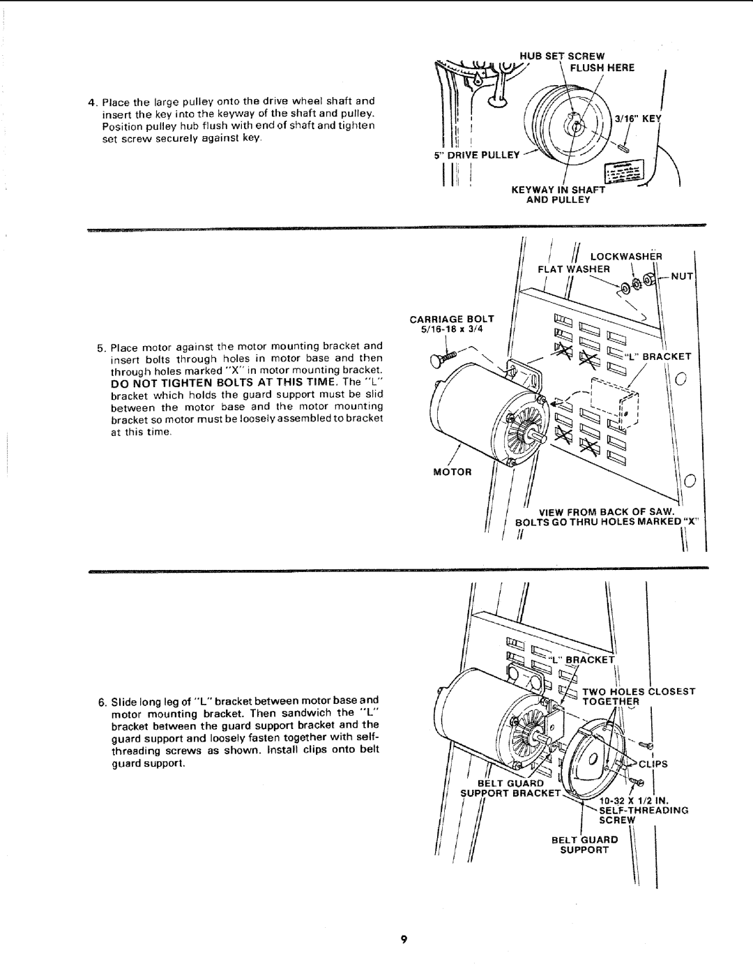
4. Place the large pulley onto the drive wheel shaft and | _" | FLUSH HER£ | ! |
insert the key into the keyway of the shaft and pulley. |
| 3/16" | KEY |
Position pulley hub flush with end of shaft and tighten |
| ||
|
|
| |
set screw securely against key. |
|
|
|
| Ilil |
|
|
| KEYWAY iN SHAFT |
| |
| AND | PULLEY |
|
/ LOCKWASHER
FLAT WASHER
CARRIAGE BOLT 5/16-18 x 3/4
5. Place motor against the motor mounting bracket and
insert bolts through holes in motor base and then through holes marked "'X" in motor mounting bracket.
DO NOT TIGHTEN BOLTS AT THIS TIME. The "'L'" bracket which holds the guard support must be slid
between the motor base and the motor mounting bracket so motor must be loosely assembled to bracket at this time.
MOTOR
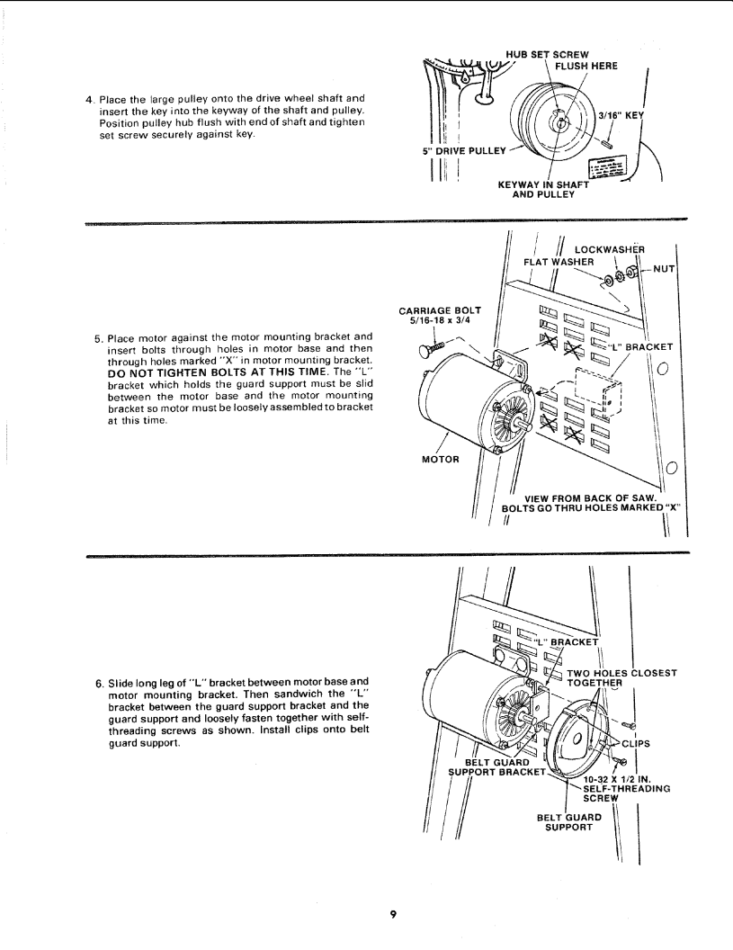
6, Slide long leg of "'L'" bracket between motor base and
motor mounting bracket. Then sandwich the "L" bracket between the guard support bracket and the guard support and loosely fasten together with self-
threading screws as shown. Install clips onto belt guard support.
VIEW FROM BACK OF SAW.
BOLTS GO THRU HOLES MARKED"X"
"/i
| : "L" | BRACKET |
|
| TWO HOLES CLOSEST |
|
| TOGETHER |
|
| J |
BELT | GUARD | I |
SUPPORT | BRACKE" |
|
|
| |
|
| """ |
|
| SCREW |
|
| SUPPORT |
BELT GUARD !i