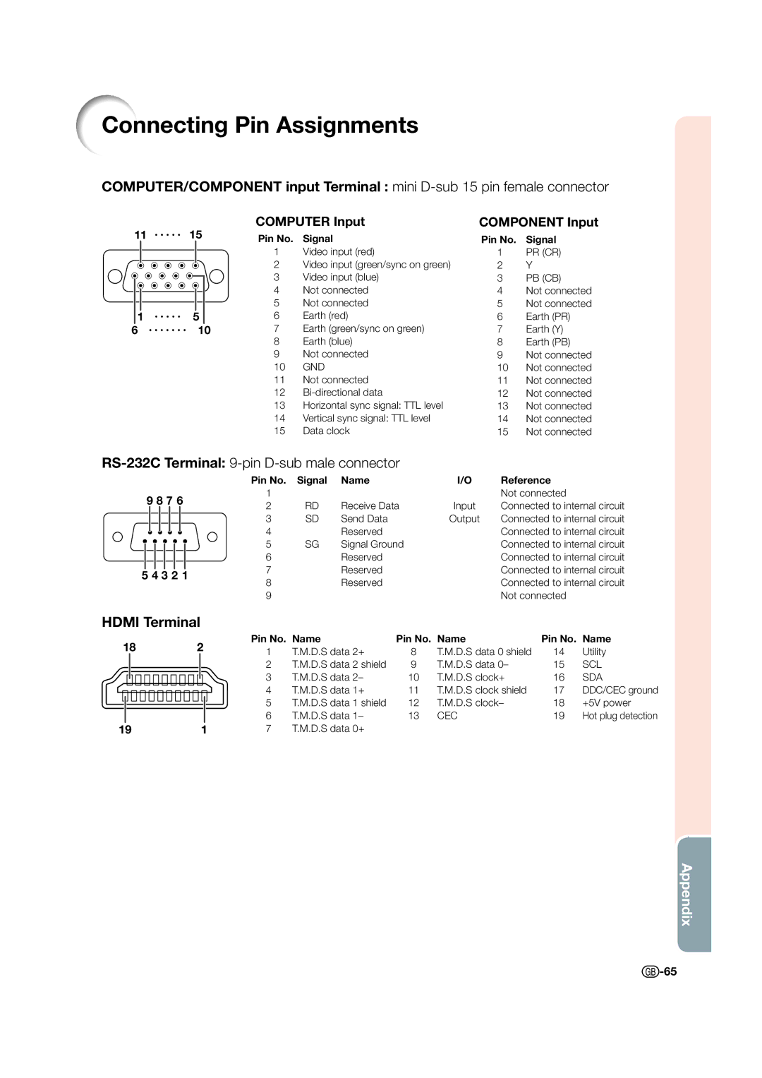
Connecting Pin Assignments
COMPUTER/COMPONENT input Terminal : mini
11 ![]()
![]()
![]()
![]()
![]() 15
15
1![]()
![]()
![]()
![]()
![]() 5
5
6 ![]()
![]()
![]()
![]()
![]()
![]()
![]() 10
10
COMPUTER Input
Pin No. Signal
1Video input (red)
2Video input (green/sync on green)
3Video input (blue)
4Not connected
5Not connected
6Earth (red)
7Earth (green/sync on green)
8Earth (blue)
9Not connected
10GND
11Not connected
12
13Horizontal sync signal: TTL level
14Vertical sync signal: TTL level
15Data clock
COMPONENT Input
Pin No. Signal
1PR (CR)
2Y
3PB (CB)
4Not connected
5Not connected
6Earth (PR)
7Earth (Y)
8Earth (PB)
9Not connected
10Not connected
11Not connected
12Not connected
13Not connected
14Not connected
15Not connected
RS-232C Terminal: 9-pin D-sub male connector
|
|
|
|
|
|
|
|
|
| Pin No. | Signal | Name | I/O | Reference |
9 | 8 7 6 |
| 1 |
|
|
| Not connected | |||||||
| 2 | RD | Receive Data | Input | Connected to internal circuit | |||||||||
|
|
|
|
|
|
|
|
|
| |||||
|
|
|
|
|
|
|
|
|
| 3 | SD | Send Data | Output | Connected to internal circuit |
|
|
|
|
|
|
|
|
|
| 4 |
| Reserved |
| Connected to internal circuit |
|
|
|
|
|
|
|
|
|
|
|
| |||
|
|
|
|
|
|
|
|
|
| 5 | SG | Signal Ground |
| Connected to internal circuit |
|
|
|
|
|
|
|
|
|
|
| ||||
|
|
|
|
|
|
|
|
|
| 6 |
| Reserved |
| Connected to internal circuit |
|
|
|
|
|
|
|
|
|
| 7 |
| Reserved |
| Connected to internal circuit |
5 4 3 2 1 |
|
| ||||||||||||
8 |
| Reserved |
| Connected to internal circuit | ||||||||||
|
|
|
|
|
|
|
|
|
|
|
| |||
|
|
|
|
|
|
|
|
|
| 9 |
|
|
| Not connected |
HDMI Terminal
182
191
Pin No. | Name | Pin No. | Name | Pin No. | Name |
1 | T.M.D.S data 2+ | 8 | T.M.D.S data 0 shield | 14 | Utility |
2 | T.M.D.S data 2 shield | 9 | T.M.D.S data 0– | 15 | SCL |
3 | T.M.D.S data 2– | 10 | T.M.D.S clock+ | 16 | SDA |
4 | T.M.D.S data 1+ | 11 | T.M.D.S clock shield | 17 | DDC/CEC ground |
5 | T.M.D.S data 1 shield | 12 | T.M.D.S clock– | 18 | +5V power |
6 | T.M.D.S data 1– | 13 | CEC | 19 | Hot plug detection |
7 | T.M.D.S data 0+ |
|
|
|
|
Appendix
![]() -65
-65