125-699 specifications
The Siemens 125-699 is a state-of-the-art industrial control product that showcases Siemens’ commitment to innovation and quality in automation technology. This device is specifically designed for various industrial applications, providing exceptional performance and reliability.One of the main features of the Siemens 125-699 is its robust processing capabilities. Equipped with a high-speed processor, it can handle complex control tasks efficiently, ensuring smooth operation even under demanding conditions. This makes it suitable for a wide range of applications, from manufacturing to process automation.
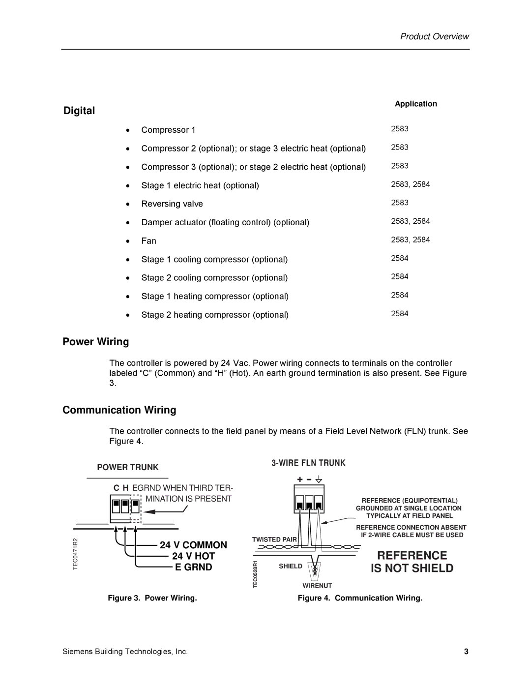
The device supports multiple communication protocols, which enhances its versatility. It is compatible with popular industrial communication standards such as Profinet, Profibus, and Ethernet/IP. This flexibility allows for seamless integration into existing systems and facilitates communication between various devices on the network, making it an ideal solution for modern interconnected factories.
In terms of user interface, the Siemens 125-699 offers an intuitive design with a user-friendly programming environment. The platform supports advanced programming languages, including Ladder Logic and Structured Text, enabling engineers to develop and modify control algorithms with ease. This capability not only improves efficiency but also reduces the time needed for troubleshooting and maintenance.
Another characteristic that sets the Siemens 125-699 apart is its rugged construction. Designed for harsh industrial environments, it features a durable housing that protects against dust, moisture, and extreme temperatures. This robustness ensures longevity and reliability, even in challenging conditions, which is crucial for minimizing downtime and promoting continuous operation.
Additionally, the Siemens 125-699 incorporates advanced diagnostic tools. These tools enable real-time monitoring of the system's performance, allowing operators to detect and address potential issues before they escalate. This proactive approach to maintenance is vital in enhancing productivity and ensuring the smooth operation of industrial processes.
In conclusion, the Siemens 125-699 is a comprehensive solution for industrial automation needs. Its combination of high processing power, versatile communication options, user-friendly interface, rugged design, and advanced diagnostic capabilities makes it a leading choice for companies looking to enhance their automation systems and improve operational efficiency. With Siemens' reputation for quality and innovation, the 125-699 stands as a testament to the company's dedication to advancing industrial technology.

