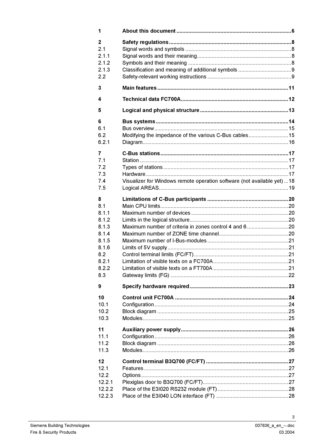
FC700A specifications
The Siemens FC700A is a cutting-edge frequency converter designed to optimize drive efficiency and enhance the performance of various applications in industrial settings. Its robust build and advanced technology make it suitable for a range of automation and control tasks, particularly in industries such as manufacturing, water treatment, and material handling.One of the main features of the FC700A is its high-performance motor control capability. The converter supports both sensorless vector control and direct torque control, allowing for precise speed regulation and enhanced torque management. This level of control is essential for applications requiring high responsiveness and accuracy, such as conveyor systems and pumps.
Additionally, the Siemens FC700A incorporates advanced communication technologies, making it highly compatible with various automation systems. It supports multiple communication protocols, including PROFINET, EtherNet/IP, and Modbus, ensuring seamless integration into existing industrial networks. This versatility simplifies the process of connecting to different types of devices and enhances overall system reliability.
Another notable characteristic of the FC700A is its energy efficiency. Designed with the latest eco-friendly technologies, the frequency converter minimizes energy consumption, reducing operational costs and environmental impact. The built-in energy-saving features, such as automatic load detection and adaptive speed control, work together to ensure optimal performance while promoting sustainability.
The FC700A also boasts an intuitive user interface, making installation and configuration straightforward. Its graphical display provides real-time monitoring of drive parameters, allowing operators to quickly assess the status of their systems. The streamlined setup process reduces downtime and facilitates maintenance routines, ensuring uninterrupted production processes.
Furthermore, the frequency converter is built to withstand harsh industrial environments. Its robust housing protects it from dust, moisture, and temperature variations, making it a reliable choice for applications in challenging conditions. The FC700A is equipped with advanced thermal management systems that ensure stable operation even under high load conditions.
In summary, the Siemens FC700A is a versatile and efficient frequency converter that excels in performance, connectivity, and robustness. With its advanced control technologies, energy-saving features, and user-friendly interface, it is an ideal solution for modern industrial applications, promoting enhanced productivity and operational excellence.
