4.6 How to reduce false echoes and shadow zones
False echoes can be produced on the radar display if the scanner is installed too close to an object on the vessel's superstructure. This object can block the radar beam and reflect it back, generating the false echoes and shadow zones.
If you're having problems with false echoes and/or shadow zones, check if it's possible to re- install the scanner at a higher location where the radar beam will be clear of any obstructions.
If not, try relocating the scanner away from the central keel line of the vessel to the starboard side. This will move any shadows to the port side, maximize the radar view of your give way sector, and ensure a clear view of the area around the vessel at the bow.
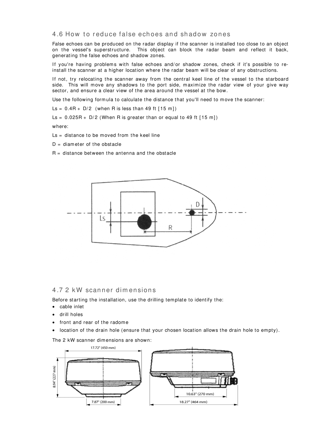
Use the following formula to calculate the distance that you'll need to move the scanner: Ls = 0.4R + D/2 (when R is less than 49 ft [15 m])
Ls = 0.025R + D/2 (When R is greater than or equal to 49 ft [15 m]) where:
Ls = distance to be moved from the keel line D = diameter of the obstacle
R = distance between the antenna and the obstacle
4.7 2 kW scanner dimensions
Before starting the installation, use the drilling template to identify the:
•cable inlet
•drill holes
•front and rear of the radome
•location of the drain hole (ensure that your chosen location allows the drain hole to empty).
The 2 kW scanner dimensions are shown:
