i n t e l l i g e n t | w i r e l e s s | p l a t f o r m |
Appendix C – Sample airHaul Bridge to Router Setup
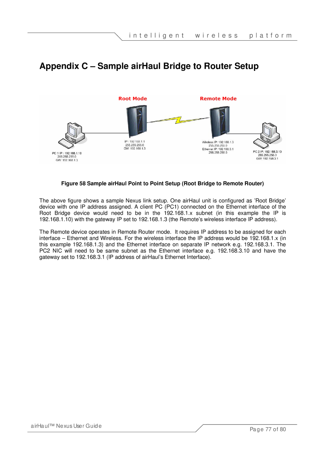
Figure 58 Sample airHaul Point to Point Setup (Root Bridge to Remote Router)
The above figure shows a sample Nexus link setup. One airHaul unit is configured as ’Root Bridge’ device with one IP address assigned. A client PC (PC1) connected on the Ethernet interface of the Root Bridge device would need to be in the 192.168.1.x subnet (in this example the IP is 192.168.1.10) with the gateway IP set to 192.168.1.3 (the Remote’s wireless interface IP address).
The Remote device operates in Remote Router mode. It requires IP address to be assigned for each interface – Ethernet and Wireless. For the wireless interface the IP address would be 192.168.1.x (in this example 192.168.1.3) and the Ethernet interface on separate IP network e.g. 192.168.3.1. The PC2 NIC will need to be same subnet as the Ethernet interface e.g. 192.168.3.10 and have the gateway set to 192.168.3.1 (IP address of airHaul’s Ethernet Interface).
airHaul™ Nexus User Guide | Page 77 of 80 |
|