“ASSEMBLY INSTRUCTIONS” |
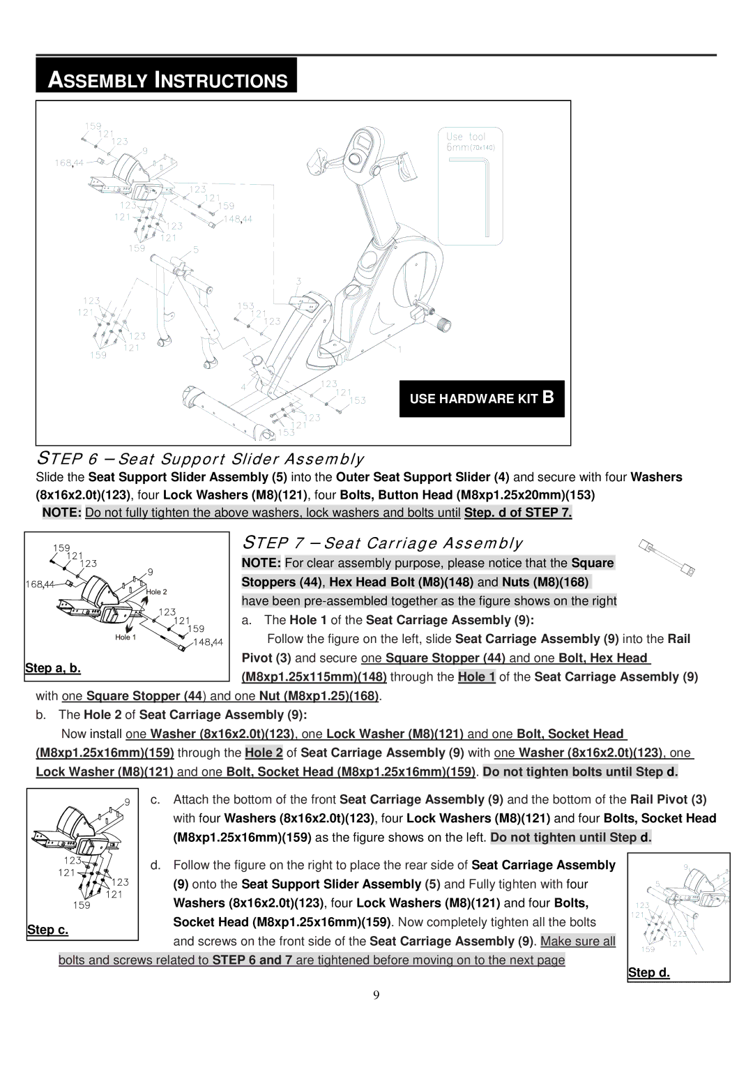
USE HARDWARE KIT B |
STEP 6 – Seat Support Slider Assembly |
Slide the Seat Support Slider Assembly (5) into the Outer Seat Support Slider (4) and secure with four Washers (8x16x2.0t)(123), four Lock Washers (M8)(121), four Bolts, Button Head (M8xp1.25x20mm)(153)
NOTE: Do not fully tighten the above washers, lock washers and bolts until Step. d of STEP 7.
STEP 7 – Seat Carriage Assembly
NOTE: For clear assembly purpose, please notice that the Square
Stoppers (44), Hex Head Bolt (M8)(148) and Nuts (M8)(168)
have been
a. The Hole 1 of the Seat Carriage Assembly (9):
Follow the figure on the left, slide Seat Carriage Assembly (9) into the Rail
Pivot (3) and secure one Square Stopper (44) and one Bolt, Hex Head (M8xp1.25x115mm)(148) through the Hole 1 of the Seat Carriage Assembly (9)
with one Square Stopper (44) and one Nut (M8xp1.25)(168).
b.The Hole 2 of Seat Carriage Assembly (9):
Now install one Washer (8x16x2.0t)(123), one Lock Washer (M8)(121) and one Bolt, Socket Head (M8xp1.25x16mm)(159) through the Hole 2 of Seat Carriage Assembly (9) with one Washer (8x16x2.0t)(123), one Lock Washer (M8)(121) and one Bolt, Socket Head (M8xp1.25x16mm)(159). Do not tighten bolts until Step d.
c. Attach the bottom of the front Seat Carriage Assembly (9) and the bottom of the Rail Pivot (3) with four Washers (8x16x2.0t)(123), four Lock Washers (M8)(121) and four Bolts, Socket Head (M8xp1.25x16mm)(159) as the figure shows on the left. Do not tighten until Step d.
d. Follow the figure on the right to place the rear side of Seat Carriage Assembly
(9) onto the Seat Support Slider Assembly (5) and Fully tighten with four Washers (8x16x2.0t)(123), four Lock Washers (M8)(121) and four Bolts, Socket Head (M8xp1.25x16mm)(159). Now completely tighten all the bolts
![]() and screws on the front side of the Seat Carriage Assembly (9). Make sure all bolts and screws related to STEP 6 and 7 are tightened before moving on to the next page
and screws on the front side of the Seat Carriage Assembly (9). Make sure all bolts and screws related to STEP 6 and 7 are tightened before moving on to the next page
Step d. |
9
