Instruction Manual
Model NGA 2000 TO2
CAUTION.
REFILLING SENSOR
When refilling the sensor, only use dis- tilled or deionized water. Do not use elec- trolyte or tap water as they can cause damage to the sensor. Take care not to overfill.
a.Refilling
To add water:
1.Remove the top cover of the ana- lyzer module.
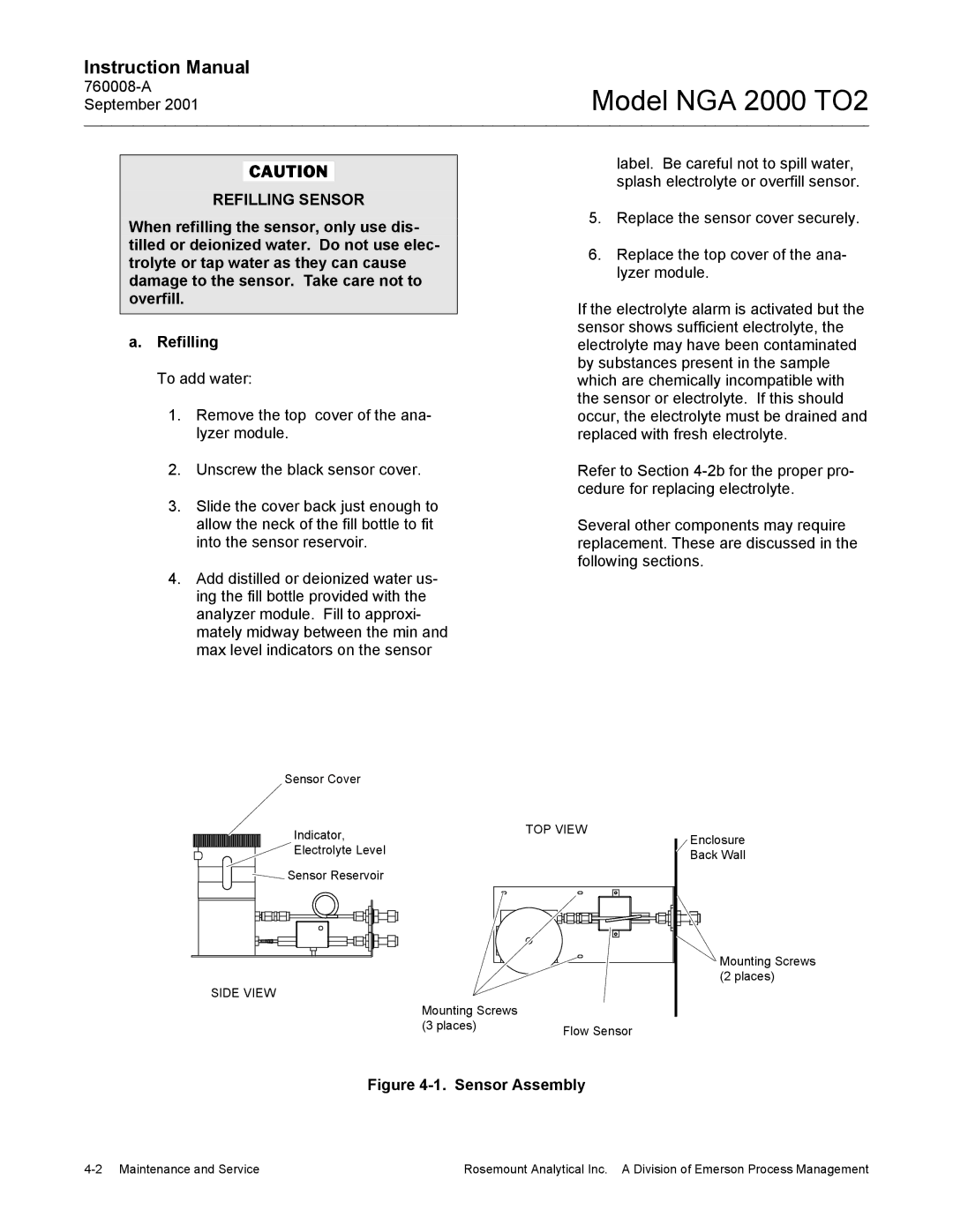
2.Unscrew the black sensor cover.
3.Slide the cover back just enough to allow the neck of the fill bottle to fit into the sensor reservoir.
4.Add distilled or deionized water us- ing the fill bottle provided with the analyzer module. Fill to approxi- mately midway between the min and max level indicators on the sensor
label. Be careful not to spill water, splash electrolyte or overfill sensor.
5.Replace the sensor cover securely.
6.Replace the top cover of the ana- lyzer module.
If the electrolyte alarm is activated but the sensor shows sufficient electrolyte, the electrolyte may have been contaminated by substances present in the sample which are chemically incompatible with the sensor or electrolyte. If this should occur, the electrolyte must be drained and replaced with fresh electrolyte.
Refer to Section
Several other components may require replacement. These are discussed in the following sections.
Sensor Cover |
|
|
|
|
|
|
|
|
|
|
|
|
|
|
|
|
|
|
|
|
| ||||||||||
| Indicator, |
|
|
|
|
|
| TOP VIEW |
|
|
|
|
|
|
| ||||||||||||||||
|
|
|
|
|
|
|
|
|
|
|
|
|
|
|
|
|
|
|
|
|
| ||||||||||
| Electrolyte Level |
|
|
|
|
|
|
|
|
|
|
|
|
|
|
|
|
|
|
|
|
| |||||||||
Sensor Reservoir |
|
|
|
|
|
|
|
|
|
|
|
|
|
|
|
|
|
|
|
|
| ||||||||||
|
|
|
|
|
|
|
|
|
|
|
|
|
|
|
|
|
|
|
|
|
|
|
|
|
|
|
|
|
|
|
|
|
|
|
|
|
|
|
|
|
|
|
|
|
|
|
|
|
|
|
|
|
|
|
|
|
|
|
|
|
|
|
|
|
|
|
|
|
|
|
|
|
|
|
|
|
|
|
|
|
|
|
|
|
|
|
|
|
|
|
|
|
|
|
|
|
|
|
|
|
|
|
|
|
|
|
|
|
|
|
|
|
|
|
|
|
|
|
|
|
|
|
|
|
|
|
|
|
|
|
|
|
|
|
|
|
|
|
|
|
|
|
|
|
|
|
|
|
|
|
|
|
|
|
|
|
|
|
|
|
|
|
|
|
|
|
|
|
|
|
|
|
|
|
|
|
|
|
|
|
|
|
|
|
|
|
|
|
|
|
|
|
|
|
|
|
|
|
|
|
|
|
|
|
|
|
|
|
|
|
|
|
|
|
|
|
|
|
|
|
|
|
|
|
|
|
|
|
|
|
|
|
|
|
|
|
|
|
|
|
|
|
|
|
|
|
|
|
|
|
|
|
|
|
|
|
|
|
|
|
|
|
|
|
|
|
|
|
|
|
|
|
|
|
|
|
|
|
|
|
|
|
|
|
|
|
|
SIDE VIEW
Mounting Screws |
|
(3 places) | Flow Sensor |
|
Enclosure |
Back Wall |
Mounting Screws |
(2 places) |
Figure 4-1. Sensor Assembly
Rosemount Analytical Inc. A Division of Emerson Process Management |
