Instruction Manual
Model NGA 2000 TO2
3-4 BASIC CONTROLS, SETUP AND STATUS
The following sections describe the basic control of the analyzer and the viewing of channel parameters. Examples of stepping through the menus are shown so that the user can become familiar with the operation,
a. Analyzer Channel Status
keeping in mind that displays and menu choices may be different depending on actual analyzer configuration and any customization of the menus.
TO2 |
|
|
|
|
|
|
|
|
|
|
|
|
| ||||
37.50 |
|
|
|
|
|
|
|
| ppm O2 |
| |||||||
|
|
|
|
|
|
|
|
|
|
|
|
|
|
|
|
|
|
0.00 |
|
|
|
|
| Range: 3 |
|
| 50.00 |
| |||||||
| Electrolyte level: |
| OK |
|
|
|
|
|
|
|
|
| |||||
| Temp current: |
| 263 uA | 0.0 |
|
|
| 100.0 |
| ||||||||
| Range: |
|
| 3 |
|
|
|
|
|
|
|
|
| ||||
|
|
|
|
|
|
|
|
|
|
| |||||||
| Sensor Current: | 0.0500 uA | 0.0000 |
|
| 100.0000 |
| ||||||||||
|
|
|
|
|
|
|
|
|
|
|
|
|
|
|
|
|
|
| Display |
|
| Status… |
| Main… |
|
| Channel |
| BasicCal |
| |||||
|
|
|
|
|
|
|
|
|
|
|
|
|
|
|
|
|
|
|
|
|
|
|
|
|
|
|
|
|
|
|
|
|
|
|
|
|
|
|
|
|
|
|
|
|
|
|
|
|
|
|
|
|
|
TO2 |
|
|
|
|
|
|
|
|
| 37.50 ppm |
| ||||||
|
|
|
|
|
|
|
|
| |||||||||
| Electrolyte level: |
|
|
|
|
|
|
|
|
| Ok |
| |||||
| Range and calibration control: |
|
|
|
|
|
| Local |
| ||||||||
| Next quick start possible after: |
|
|
|
|
|
|
| 0 s |
| |||||||
| Operation status: |
|
|
|
|
|
|
|
| Normal |
| ||||||
| Sensor current: |
|
|
|
|
|
|
| 0.0500 uA |
| |||||||
| Sensor temperature: |
|
|
|
|
|
|
|
| 25.3 °C |
| ||||||
| Sensor model: |
|
|
|
|
|
|
| |||||||||
| Over range: |
|
|
|
|
|
|
|
|
|
|
| No |
| |||
| Power supply voltages… |
|
|
|
|
|
|
|
|
| |||||||
|
|
|
|
|
|
|
|
|
|
|
|
|
|
|
|
| |
Measure |
|
| Back… |
|
|
|
|
|
|
|
|
|
|
| |||
|
|
|
|
|
|
|
|
|
|
|
|
|
|
|
|
|
|
|
|
|
|
|
|
|
|
|
|
|
|
|
|
|
|
|
|
TO2 |
|
|
|
|
|
|
|
|
| 37.50 ppm |
| ||||||
|
|
|
|
|
|
|
|
|
| ||||||||
| +15V analog: |
|
|
|
|
|
|
|
| 14.9V |
| ||||||
|
|
|
|
|
|
|
|
|
| ||||||||
| +5V digital: |
|
|
|
|
|
|
|
|
|
| 5.02V |
| ||||
| +24V power: |
|
|
|
|
|
|
|
| 23.89V |
| ||||||
| Primary electrode: |
|
|
|
|
|
|
|
| 1.31V |
| ||||||
| Isolated 15V: |
|
|
|
|
|
|
|
|
| OK |
| |||||
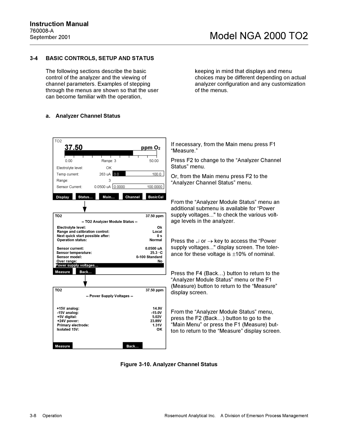
If necessary, from the Main menu press F1 “Measure.”
Press F2 to change to the “Analyzer Channel Status” menu.
Or, from the Main menu press F2 to the “Analyzer Channel Status” menu.
From the “Analyzer Module Status” menu an additional submenu is available for “Power supply voltages..." to check the various volt- age levels in the analyzer.
Press the ↵ or → key to access the “Power supply voltages..." display screen. The toler- ance for these voltage is ±10% of nominal.
Press the F4 (Back…) button to return to the “Analyzer Module Status” menu or the F1 (Measure) button to return to the “Measure” display screen.
From the “Analyzer Module Status” menu, press the F2 (Back…) button to go to the “Main Menu” or press the F1 (Measure) but- ton to return to the “Measure” display screen.
Measure
Back…
Figure 3-10. Analyzer Channel Status
Rosemount Analytical Inc. A Division of Emerson Process Management |
