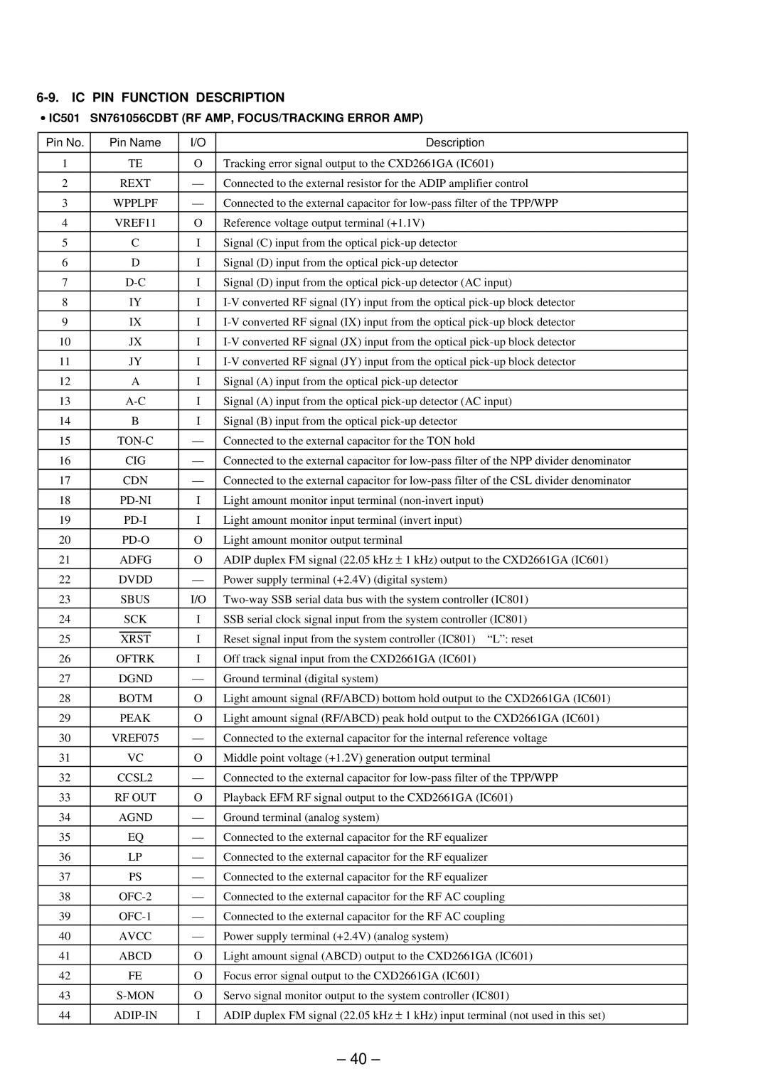
6-9. IC PIN FUNCTION DESCRIPTION
•IC501 SN761056CDBT (RF AMP, FOCUS/TRACKING ERROR AMP)
Pin No. |
| Pin Name | I/O | Description | |
|
|
|
|
|
|
1 |
|
| TE | O | Tracking error signal output to the CXD2661GA (IC601) |
|
|
|
|
|
|
2 |
| REXT | — | Connected to the external resistor for the ADIP amplifier control | |
|
|
|
|
|
|
3 |
| WPPLPF | — | Connected to the external capacitor for | |
|
|
|
|
|
|
4 |
| VREF11 | O | Reference voltage output terminal (+1.1V) | |
|
|
|
|
|
|
5 |
|
| C | I | Signal (C) input from the optical |
|
|
|
|
|
|
6 |
|
| D | I | Signal (D) input from the optical |
|
|
|
|
|
|
7 |
|
| I | Signal (D) input from the optical | |
|
|
|
|
|
|
8 |
|
| IY | I | |
|
|
|
|
|
|
9 |
|
| IX | I | |
|
|
|
|
|
|
10 |
|
| JX | I | |
|
|
|
|
|
|
11 |
|
| JY | I | |
|
|
|
|
|
|
12 |
|
| A | I | Signal (A) input from the optical |
|
|
|
|
|
|
13 |
|
| I | Signal (A) input from the optical | |
|
|
|
|
|
|
14 |
|
| B | I | Signal (B) input from the optical |
|
|
|
|
|
|
15 |
| — | Connected to the external capacitor for the TON hold | ||
|
|
|
|
|
|
16 |
|
| CIG | — | Connected to the external capacitor for |
|
|
|
|
|
|
17 |
| CDN | — | Connected to the external capacitor for | |
|
|
|
|
|
|
18 |
| I | Light amount monitor input terminal | ||
|
|
|
|
|
|
19 |
|
| I | Light amount monitor input terminal (invert input) | |
20 |
| O | Light amount monitor output terminal | ||
|
|
|
|
|
|
21 |
| ADFG | O | ADIP duplex FM signal (22.05 kHz ± 1 kHz) output to the CXD2661GA (IC601) | |
22 |
| DVDD | — | Power supply terminal (+2.4V) (digital system) | |
|
|
|
|
|
|
23 |
| SBUS | I/O | ||
|
|
|
|
|
|
24 |
| SCK | I | SSB serial clock signal input from the system controller (IC801) | |
|
|
|
|
|
|
25 |
| XRST | I | Reset signal input from the system controller (IC801) “L”: reset | |
|
|
|
|
| |
26 |
| OFTRK | I | Off track signal input from the CXD2661GA (IC601) | |
|
|
|
|
| |
27 |
| DGND | — | Ground terminal (digital system) | |
|
|
|
|
| |
28 |
| BOTM | O | Light amount signal (RF/ABCD) bottom hold output to the CXD2661GA (IC601) | |
|
|
|
|
| |
29 |
| PEAK | O | Light amount signal (RF/ABCD) peak hold output to the CXD2661GA (IC601) | |
|
|
|
|
| |
30 |
| VREF075 | — | Connected to the external capacitor for the internal reference voltage | |
|
|
|
|
|
|
31 |
|
| VC | O | Middle point voltage (+1.2V) generation output terminal |
|
|
|
|
| |
32 |
| CCSL2 | — | Connected to the external capacitor for | |
|
|
|
|
| |
33 |
| RF OUT | O | Playback EFM RF signal output to the CXD2661GA (IC601) | |
|
|
|
|
| |
34 |
| AGND | — | Ground terminal (analog system) | |
|
|
|
|
|
|
35 |
|
| EQ | — | Connected to the external capacitor for the RF equalizer |
|
|
|
|
|
|
36 |
|
| LP | — | Connected to the external capacitor for the RF equalizer |
|
|
|
|
|
|
37 |
|
| PS | — | Connected to the external capacitor for the RF equalizer |
|
|
|
|
| |
38 |
| — | Connected to the external capacitor for the RF AC coupling | ||
|
|
|
|
| |
39 |
| — | Connected to the external capacitor for the RF AC coupling | ||
|
|
|
|
| |
40 |
| AVCC | — | Power supply terminal (+2.4V) (analog system) | |
41 |
| ABCD | O | Light amount signal (ABCD) output to the CXD2661GA (IC601) | |
|
|
|
|
|
|
42 |
|
| FE | O | Focus error signal output to the CXD2661GA (IC601) |
|
|
|
|
| |
43 |
| O | Servo signal monitor output to the system controller (IC801) | ||
|
|
|
|
| |
44 |
| I | ADIP duplex FM signal (22.05 kHz ± 1 kHz) input terminal (not used in this set) | ||
|
|
|
|
|
|
– 40 –