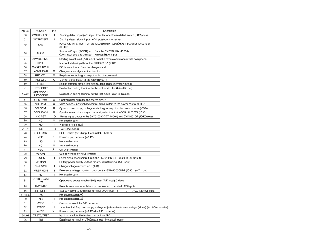
Pin No. | Pin Name | I/O | Description | ||
|
|
|
| ||
50 | XWAKE CLOSE | I | Starting detect input (A/D input) from the open/close detect switch (S809) “L”: close | ||
|
|
|
| ||
51 | XWAKE SET | I | Starting detect signal input (A/D input) from the set key | ||
|
|
|
| ||
52 | FOK | I | Focus OK signal input from the CXD2661GA (IC601) “H” is input when focus is on | ||
(“L”: NG) |
| ||||
|
|
|
| ||
|
|
|
| ||
53 | SQSY | I | Subcode Q sync (SCOR) input from the CXD2661GA (IC601) | ||
“L” is input every 13.3 msec. Almost all, “H” is input | |||||
|
|
| |||
|
|
|
| ||
54 | XWAKE RMC | I | Starting detect input (A/D input) from the remote commander with headphone | ||
55 | XINT | I | Interrupt status input from the CXD2661GA (IC601) | ||
56 | XWAKE DC IN | I | DC IN detect input from the charge stand |
| |
|
|
|
|
| |
57 | XCHG PWR | O | Charge control signal output terminal |
| |
|
|
|
|
| |
58 | REC CTL | O | Regulator control signal output to the charge stand |
| |
|
|
|
|
| |
59 | RLY CTL | O | Control signal output to the relay (RY901) |
| |
|
|
|
| ||
60 | XTEST | I | Setting terminal for the test mode “L”: test mode (normally: open) | ||
61 | SET CODE0 | I | Destination setting terminal for the test mode (fixed at “L” in this set) | ||
62,63 | SET CODE1, | I | Destination setting terminal for the test mode (open in this set) | ||
SET CODE2 | |||||
|
|
|
| ||
|
|
|
|
| |
64 | CHG PWM | O | Control signal output to the charge circuit |
| |
|
|
|
| ||
65 | VR PWM | O | VRM power supply voltage control signal output to the power control (IC907) | ||
|
|
|
| ||
66 | VC PWM | O | System power supply voltage control signal output to the power control (IC904) | ||
|
|
|
| ||
67 | SPDL PWM | O | Spindle servo drive voltage control signal output to the XC111256FTA (IC551) | ||
68 | XIC RST | O | Reset signal output to the SN761056CDBT (IC501) and CXD2661GA (IC601) “L”: reset | ||
69 | NC | O | Not used (open) |
| |
|
|
|
|
| |
70 | NC | I | Not used (fixed at “L”) |
| |
|
|
|
|
| |
71, 72 | NC | O | Not used (open) |
| |
|
|
|
|
| |
73 | XHOLD SW | I | HOLD switch (S808) input terminal “L”: hold on |
| |
|
|
|
|
| |
74 | VDD | — | Power supply terminal (+2.4V) |
| |
75 | NC | I | Not used (open) |
| |
76 | NC | O | Not used (open) |
| |
|
|
|
|
| |
77 | VSS | — | Ground terminal |
| |
|
|
|
|
| |
78 | VBKAN | I | Sub power supply input terminal |
| |
|
|
|
| ||
79 | S MON | I | Servo signal monitor input from the SN761056CDBT (IC501) (A/D input) | ||
|
|
|
| ||
80 | VB MON | I | Battery power supply voltage monitor input terminal (A/D input) | ||
81 | CHG MON | I | Charge voltage monitor input (A/D) |
| |
82 | VREF MON | I | Reference voltage monitor input from the SN761056CDBT (IC501) (A/D input) | ||
|
|
|
|
| |
83 | NC | I | Not used (open) |
| |
|
|
|
|
| |
84 | OPEN CLOSE | I | Open/close detect switch (S809) input (A/D input) | “L”: close | |
SW | |||||
|
|
|
| ||
|
|
|
| ||
85 | RMC KEY | I | Remote commander with headphone key input terminal (A/D input) | ||
|
|
|
|
| |
86 | SET KEY 1 | I | Set key (S801 to 805) input terminal (A/D input) | (x, > N, .,VOL +/– keys input) | |
87 to 89 | NC | I | Not used (fixed at “H”) |
| |
90 | NC | I | Not used (fixed at “L”) |
| |
|
|
|
|
| |
91 | AVSS | — | Ground terminal (for A/D converter) |
| |
|
|
|
| ||
92 | AVREF | I | Input terminal for power supply voltage adjustment reference voltage (+2.4V) (for A/D converter) | ||
|
|
|
|
| |
93 | AVDD | — | Power supply terminal (+2.4V) (for A/D converter) |
| |
|
|
|
|
| |
94, 95 | TEST0, TEST1 | I | Input terminal for the test (normally: fixed at “L”) |
| |
96 | TDI | I | Data input terminal for JTAG scan test Not used (open) | ||
– 45 –
