EVS Toolroom Lathes | S E R V I C E | For Machines Mfg. Since 7/09 |
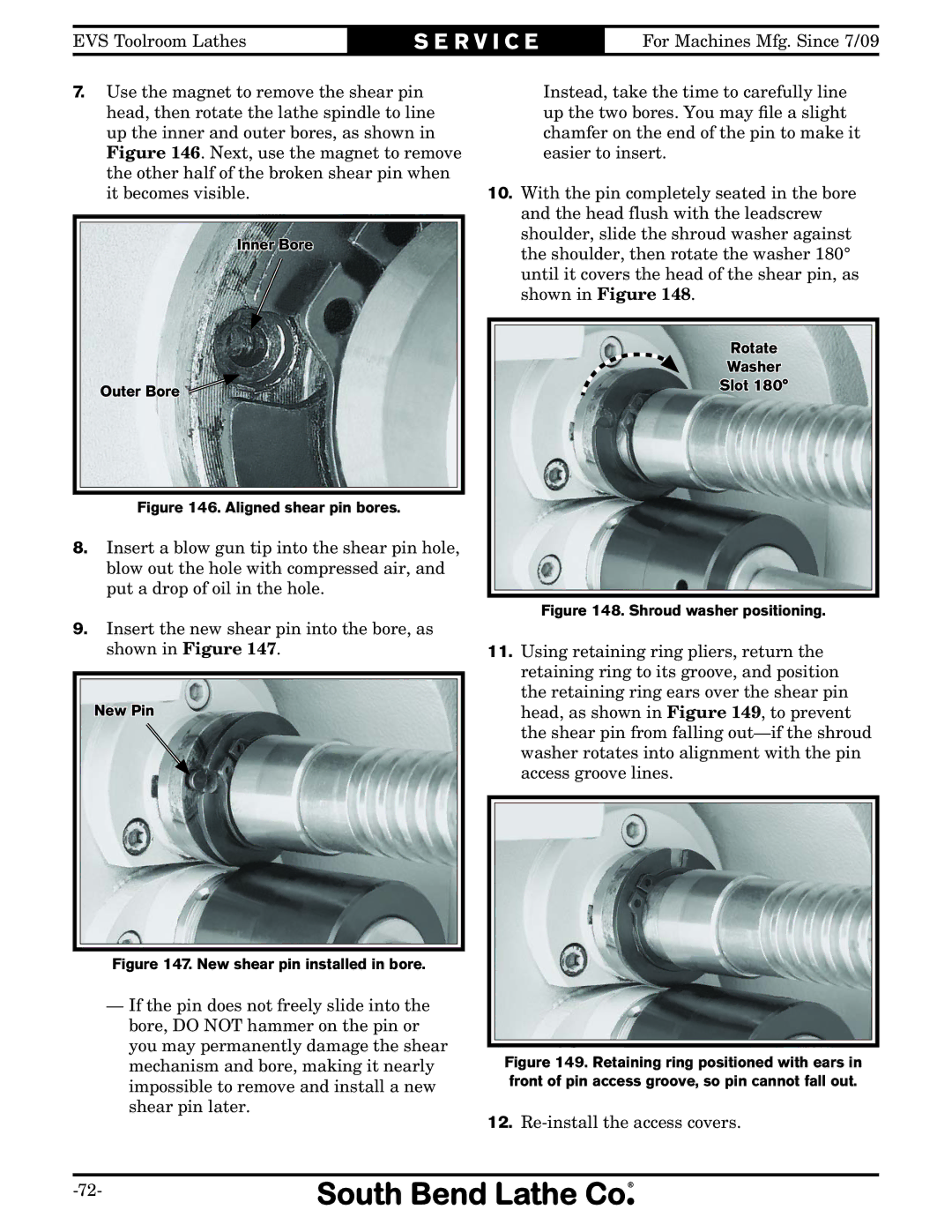
7.Use the magnet to remove the shear pin head, then rotate the lathe spindle to line up the inner and outer bores, as shown in Figure 146. Next, use the magnet to remove the other half of the broken shear pin when it becomes visible.
Inner Bore
Outer Bore
Figure 146. Aligned shear pin bores.
8.Insert a blow gun tip into the shear pin hole, blow out the hole with compressed air, and put a drop of oil in the hole.
9.Insert the new shear pin into the bore, as shown in Figure 147.
New Pin
Figure 147. New shear pin installed in bore.
—If the pin does not freely slide into the bore, DO NOT hammer on the pin or you may permanently damage the shear mechanism and bore, making it nearly impossible to remove and install a new shear pin later.
Instead, take the time to carefully line up the two bores. You may file a slight chamfer on the end of the pin to make it easier to insert.
10.With the pin completely seated in the bore and the head flush with the leadscrew shoulder, slide the shroud washer against the shoulder, then rotate the washer 180° until it covers the head of the shear pin, as shown in Figure 148.
Rotate
Washer
Slot 180°
Figure 148. Shroud washer positioning.
11.Using retaining ring pliers, return the retaining ring to its groove, and position the retaining ring ears over the shear pin head, as shown in Figure 149, to prevent the shear pin from falling