EVS Toolroom Lathes | O P E R A T I O N | For Machines Mfg. Since 7/09 |
Setting Spindle Speed
1.Make sure the spindle is turned OFF and it has come to a complete stop.
2.Use the chart in Figure 79 to determine the available spindle speed range closest to your calculated spindle speed.
| SPEEDS | |
LEVER |
| RPM |
Low |
| |
High |
| |
Figure 79. Spindle speed range chart.
If the headstock is in high range
3.Adjust the spindle speed range lever to the range that covers your calculated spindle speed.
Note: To shift the spindle speed range lever, you may need to apply pressure to the lever and slightly rotate the spindle by hand.
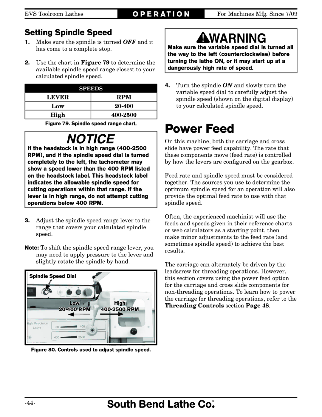
Spindle Speed Dial
Low | High | |
|
|
|
|
|
|
Figure 80. Controls used to adjust spindle speed.
Make sure the variable speed dial is turned all the way to the left (counterclockwise) before turning the lathe ON, or it may start up at a dangerously high rate of speed.
4.Turn the spindle ON and slowly turn the variable speed dial to carefully adjust the spindle speed (shown on the digital display) to your calculated spindle speed.
Power Feed
On this machine, both the carriage and cross slide have power feed capability. The rate that these components move (feed rate) is controlled by how the levers are configured on the gearbox.
Feed rate and spindle speed must be considered together. The sources you use to determine the optimum spindle speed for an operation will also provide the optimal feed rate to use with that spindle speed.
Often, the experienced machinist will use the feeds and speeds given in their reference charts or web calculators as a starting point, then make minor adjustments to the feed rate (and sometimes spindle speed) to achieve the best results.
The carriage can alternately be driven by the leadscrew for threading operations. However, this section covers using the power feed option for the carriage and cross slide components for