Model SB1018 | P R E P A R A T I O N | For Machines Mfg. Since 8/09 |
Description (Figure 5) | Qty | |
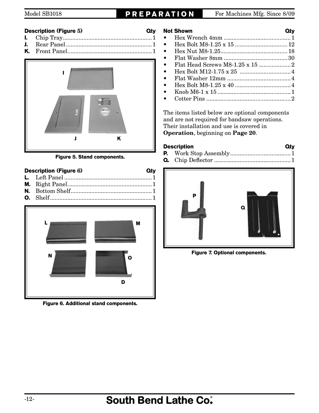
I. | Chip Tray | 1 |
J. | Rear Panel | 1 |
K. | Front Panel | 1 |
| I |
|
| J | K |
| Figure 5. Stand components. | |
Description (Figure 6) | Qty | |
L. | Left Panel | 1 |
M. | Right Panel | 1 |
N. | Bottom Shelf | 1 |
O. | Shelf | 1 |
| L | M |
| N |
|
|
| O |
|
| D |
Not Shown | Qty | |
• | Hex Wrench 4mm | 1 |
• Hex Bolt | 12 | |
• | Hex Nut | 18 |
• | Flat Washer 8mm | 30 |
• Flat Head Screws | 2 | |
• Hex Bolt | 4 | |
• | Flat Washer 12mm | 4 |
• Hex Bolt | 4 | |
• Knob | 1 | |
• | Cotter Pins | 2 |
The items listed below are optional components and are not required for bandsaw operations. Their installation and use is covered in Operation, beginning on Page 20.
Description | Qty | |
P. | Work Stop Assembly | ....................................... 1 |
Q. | Chip Deflector | 1 |
P
Q