Model SB1018 | P R E P A R A T I O N | For Machines Mfg. Since 8/09 |
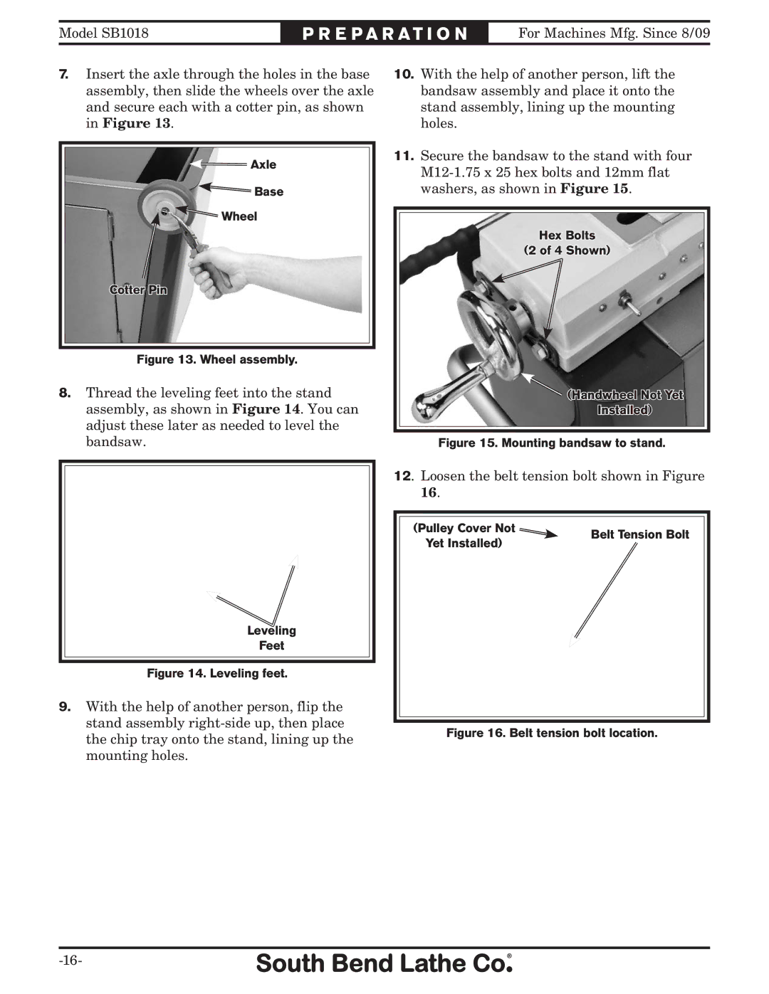
7.Insert the axle through the holes in the base assembly, then slide the wheels over the axle and secure each with a cotter pin, as shown in Figure 13.
![]() Axle
Axle
![]() Base
Base
![]() Wheel
Wheel
Cotter Pin
Figure 13. Wheel assembly.
8.Thread the leveling feet into the stand assembly, as shown in Figure 14. You can adjust these later as needed to level the bandsaw.
Leveling
Feet
Figure 14. Leveling feet.
9.With the help of another person, flip the stand assembly
10.With the help of another person, lift the bandsaw assembly and place it onto the stand assembly, lining up the mounting holes.
11.Secure the bandsaw to the stand with four
Hex Bolts
(2 of 4 Shown)
![]() (Handwheel Not Yet
(Handwheel Not Yet
Installed)
Figure 15. Mounting bandsaw to stand.
12. Loosen the belt tension bolt shown in Figure
16.
(Pulley Cover Not | Belt Tension Bolt | |
Yet Installed) | ||
|