For Machines Mfg. Since 8/09 | O P E R A T I O N | Model SB1040/SB1041 |
Note: To make a proper blade weld, the ends of the blade must be evenly butted together during the welding process. If necessary, use the grinder to square up the ends or remove any teeth that are in the welding zone (see Figures
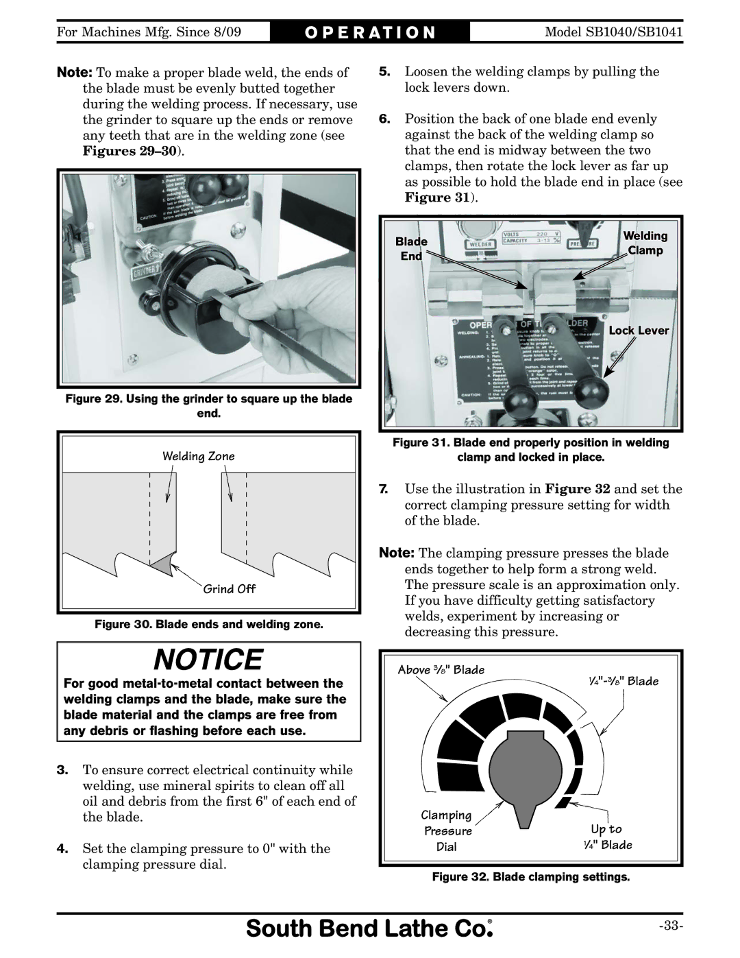
Figure 29. Using the grinder to square up the blade
end.
Welding Zone |
Grind Off |
Figure 30. Blade ends and welding zone.
5.Loosen the welding clamps by pulling the lock levers down.
6.Position the back of one blade end evenly against the back of the welding clamp so that the end is midway between the two clamps, then rotate the lock lever as far up as possible to hold the blade end in place (see Figure 31).
Blade | Welding | |
Clamp | ||
End | ||
| ||
| Lock Lever |
Figure 31. Blade end properly position in welding
clamp and locked in place.
7.Use the illustration in Figure 32 and set the correct clamping pressure setting for width of the blade.
Note: The clamping pressure presses the blade ends together to help form a strong weld. The pressure scale is an approximation only. If you have difficulty getting satisfactory welds, experiment by increasing or decreasing this pressure.
For good
3.To ensure correct electrical continuity while welding, use mineral spirits to clean off all oil and debris from the first 6" of each end of the blade.
4.Set the clamping pressure to 0" with the clamping pressure dial.
Above 3⁄8" Blade
1⁄4"-3⁄8" Blade
Clamping | Up to |
Pressure | |
Dial | 1⁄4" Blade |