17
5.1.1. Current Recording Screen
Show the images of the connected cameras. Each channel number of the connected camera and channel name set by the user will be indicated. According to the screen status (security screen mode, watch mode), the image will appear and a mark (M / C / M, S / C, S / S / F/ P, S) will be on the right bottom of each channel image. Refer to “Preference” for channel name and recording settings. To enter each channel name, press the [Setup] button from the main screen and go to [Camera]→[Camera Name] to enter the necessary content. Refer to the explanation for [Preference]→[Camera] tap.
1
2
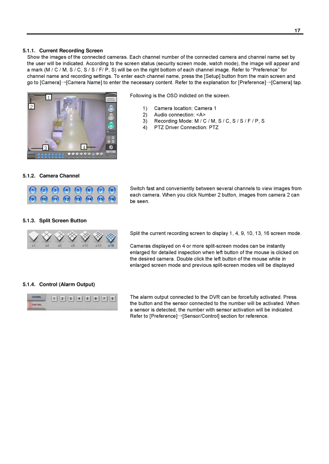
Following is the OSD indicted on the screen.
1)Camera location: Camera 1
2)Audio connection: <A>
3)Recording Mode: M / C / M, S / C, S / S / F / P, S
4)PTZ Driver Connection: PTZ
3
4
5.1.2. Camera Channel
Switch fast and conveniently between several channels to view images from each camera. When you click Number 2 button, images from camera 2 can be seen.
5.1.3. Split Screen Button
Split the current recording screen to display 1, 4, 9, 10, 13, 16 screen mode.
Cameras displayed on 4 or more
5.1.4. Control (Alarm Output)
The alarm output connected to the DVR can be forcefully activated. Press the button and the sensor connected to the number will be activated. When a sensor is detected, the number with sensor activation will be indicated. Refer to [Preference]→[Sensor/Control] section for reference.
